Three-Phase Meter
Description of the Three-phase Meter component capable of measuring currents, voltages, frequency and power of a three-phase system.
Component Introduction
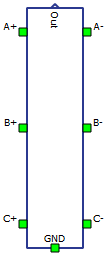
The Three-phase Meter component is part of the fundamental set of measurements available in Schematic Editor. Three-phase Meter measures currents, voltages, frequency and power of a three-phase system. It outputs the measured values through signal processing output, and/or makes them available via internal probes. The output is a vectorized fixed-size output. Within the properties window of the meter, different measurements can be enabled/disabled. It is recommended to enable only the measurements that are required, to save computational resources. Measurements that are not selected will be automatically set to zero in the output vector.
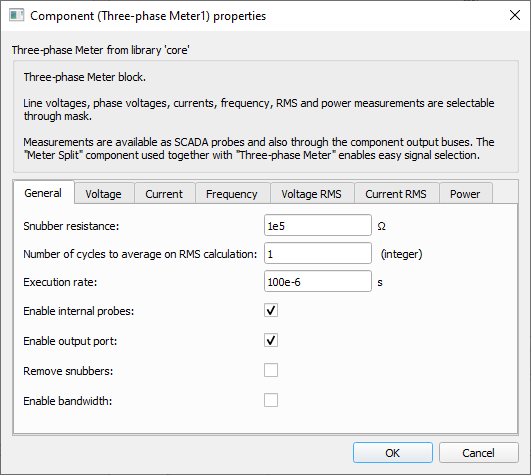
Tab: "General"
In this tab, the snubber resistance, number of cycles to average on RMS calculations and execution rate can be set. It is also possible to enable internal probes, enable output port, remove the snubbers and enable/set bandwidth.
- Number of cycles to average on RMS calculation
- Number of cycles to use when calculating RMS. This results in an RMS measurement average over "n_cycles". [Integer]. Increasing the number of cycles to average during RMS calculation increases the measurement precision at the cost of increased delay to output a new measurement value.
- Code name: n_cycles
- Enable internal probes
- Checkbox that enables the placement of internal probes for active measurements. Set as True by default.
-
Extra PLL measurements can only be made available if this property is set to True.
- Code name: enable_probes
- Enable output port
- Checkbox that enables an output port for all measurements that are active with the exception of the per-phase power measurements from the "RMS Based" method. Set as True by default.
- Code name: enable_out
- Remove snubbers
- Checkbox that removes snubber resistors that are used to generate a reference point to the phase-to-neutral voltage measurements.
- When set to True, the property Snubber resistance is disabled. Set as False by default.
-
Important: When this property is set to True, the user must connect the ground port to a valid reference, otherwise measurements will be compromised.
- Code name: remove_snubber
- Snubber resistance
- Editable if Remove snubbers is set to False
- Snubber resistance value. Snubber resistors are connected in parallel to the phase voltage measurements. [Ω]
- Code name: R
- Enable bandwidth
- Checkbox that enables the bandwidth setting for instantaneous voltage and current measurements.
- When set to True, the property Bandwidth is shown and enabled. Set as False by default.
- Code name: enable_bandwidth
- Bandwidth
- Available if Enable bandwidth is set to True
- Bandwidth of the low pass filter of the instantaneous voltage and current measurements. This property is hidden by default. [Hz]
- Code name: bandwidth
- Execution rate
- Execution rate of the inner signal processing components. [s]
- Code name: execution_rate
Tab: "Instantaneous"
In this properties tab, instantaneous voltage, current and frequency measurements can be enabled.
- Phase voltage measurement (A)
- Checkbox that enables the measurement of phase A's instantaneous voltage.
- Code name: VAn
- Phase voltage measurement (B)
- Checkbox that enables the measurement of phase B's instantaneous voltage.
- Code name: VBn
- Phase voltage measurement (C)
- Checkbox that enables the measurement of phase C's instantaneous voltage.
- Code name: VCn
- Line voltage measurement (AB)
- Checkbox that enables the measurement of A-B line's instantaneous voltage.
- Code name: VAB
- Line voltage measurement (BC)
- Checkbox that enables the measurement of B-C line's instantaneous voltage.
- Code name: VBC
- Line voltage measurement (CA)
- Checkbox that enables the measurement of C-A line's instantaneous voltage.
- Code name: VCA
- Estimated neutral voltage measurement (N)
- Checkbox that enables the instantaneous neutral voltage estimation by summing the line-to-neutral three-phase voltages.
- Requires ABC instantaneous phase-to-neutral voltage measurements.
- Code name: VN
- Phase current measurement (A)
- Checkbox that enables the measurement of phase A's instantaneous current.
- Code name: IA
- Phase current measurement (B)
- Checkbox that enables the measurement of phase B's instantaneous current.
- Code name: IB
- Phase current measurement (C)
- Checkbox that enables the measurement of phase C's instantaneous current.
- Code name: IC
- Estimated neutral current measurement (N)
- Checkbox that enables the instantaneous neutral current estimation by summing the three-phase currents.
- Requires ABC instantaneous phase current measurements.
- Code name: IN
- Frequency measurement
- Checkbox that enables the frequency measurement using a three-phase PLL component.
-
Requires ABC instantaneous phase-to-neutral voltage measurements.
-
With the frequency measurement set to True, other PLL measurements, such as Vd, Vq, Vz, Vpeak, wt, and sin_wt, can be set to active.
- Code name: freq
- Direct voltage measurement (Vd)
-
Enabled if the properties Frequency and Enable internal probes are set.
- Checkbox that enables the direct voltage measurement from the dq frame of the three-phase PLL.
- Hidden by default.
- Not made available through output ports, only through probes.
-
Requires Frequency measurement.
- Code name: Vd
-
- Quadrature voltage measurement (Vq)
-
Enabled if the properties Frequency and Enable internal probes are set.
- Checkbox that enables the quadrature voltage measurement from the dq frame of the three-phase PLL.
- Hidden by default.
- Not made available through output ports, only through probes.
-
Requires Frequency measurement.
- Code name: Vq
-
- Zero voltage measurement (Vz)
-
Enabled if the properties Frequency and Enable internal probes are set.
- Checkbox that enables the zero voltage measurement from the dq frame of the three-phase PLL.
- Hidden by default.
- Not made available through output ports, only through probes.
-
Requires Frequency measurement.
- Code name: Vz
-
- Peak voltage measurement (Vpeak)
-
Enabled if the properties Frequency and Enable internal probes are set.
- Checkbox that enables the peak voltage measurement ( ) from the dq frame of the three-phase PLL.
- Hidden by default.
- Not made available through output ports, only through probes.
-
Requires Frequency measurement.
- Code name: Vpeak
-
- Phase angle measurement (wt)
-
Enabled if the properties Frequency and Enable internal probes are set.
- Checkbox that enables the phase angle measurement from the three-phase PLL.
- Hidden by default.
- Not made available through output ports, only through probes.
-
Requires Frequency measurement.
- Code name: wt
-
- Sine of phase angle measurement (sin_wt)
-
Enabled if the properties Frequency and Enable internal probes are set.
- Checkbox that enables the sine of the phase angle measurement from the three-phase PLL.
- Hidden by default.
- Not made available through output ports, only through probes.
-
Requires Frequency measurement.
- Code name: sin_wt
-
Tab: "RMS"
- Phase voltage measurements (VAn, VBn, VCn)
- Checkbox that enables the RMS measurements of the three-phase phase voltages (VAn, VBn and VCn).
- Requires frequency and ABC instantaneous voltage measurements.
- Code name: VLn_rms
- Line voltage measurement (VAB, VBC, VCA)
- Checkbox that enables the RMS measurements of the three-phase line voltages (VAB, VBC and VCA).
- Requires frequency and instantaneous AB-BC-CA voltage measurements.
- Code name: VLL_rms
- Average phase voltage RMS measurement (VLn)
- Checkbox that enables the average RMS measurement of the three-phase phase voltages.
- Requires three-phase phase-to-neutral RMS voltage measurements.
- Code name: VLn_avg_rms
- Average line voltage RMS measurement (VLL)
- Checkbox that enables the average RMS measurement of the three-phase line voltages.
-
Requires three-phase phase-to-phase RMS voltage measurements.
- Code name: VLL_avg_rms
- Estimated neutral voltage RMS measurement (VN)
- Checkbox that enables the RMS measurement of the estimated neutral voltage.
-
Requires frequency and estimated instantaneous neutral voltage measurements.
- Code name: VN_rms
- Phase current RMS measurements (IA, IB, IC)
- Checkbox that enables the RMS measurement of the three-phase phase currents (IA, IB, and IC).
-
Requires frequency and instantaneous three-phase current measurements.
- Code name: I_rms
- Average phase current RMS measurement (I)
- Checkbox that enables the average RMS measurement of the three-phase phase currents.
-
Requires three-phase RMS current measurements.
- Code name: I_avg_rms
- Estimated neutral current RMS measurement (IN)
- Checkbox that enables the RMS measurement of the estimated neutral current.
- Requires frequency and estimated instantaneous neutral current measurements.
- Code name: IN_rms
Tab: "Power"
- Power measurement method
- Combo box that enables the selection between two different power measurement
methods.
- alpha-beta: uses three-phase phase-to-neutral voltages and phase currents for the power computation using alpha-beta transformation. When this option is selected, properties for filter configuration and instantaneous power measurements are made visible.
- RMS based: uses three-phase RMS phase-to-neutral voltage and phase current, and frequency measurements to calculate power. This method provides per-phase power measurements.
- Code name: P_method
- Combo box that enables the selection between two different power measurement
methods.
- Power measurement
- Checkbox that enables the power measurement according to the Power measurement method chosen.
- Code name: P_meas
- Enable extra output port
- Enabled if Power measurement method is set to RMS based.
- Checkbox that enables an extra output port.
- The extra output port only contains per-phase power information.
- Code name: enable_extra_out
- Low pass filter order
- Available if Power measurement method is set to alpha-beta.
- Combo box that enables the selection of the type of low pass filter used for the
alpha-beta power measurement.
- no filter: use no filters on the power computation method.
- first order: use a first order low pass filter on the power computation method. The cutoff frequency is defined by the property Filter cutoff frequency.
- second order: use a second order low pass filter on the power computation method. The cutoff frequency is defined by the property Filter cutoff frequency.
- Code name: filter_order
- Filter cutoff frequency
- Available if Power measurement method is set to alpha-beta.
- Low pass filter cutoff frequency. This property is disabled when Low pass filter order is defined as no filter. This property define the cutoff frequencies for both first and second order filter options.
- Code name: filter_cutoff_Hz
- Instantaneous power
- Available if Power measurement method is set to alpha-beta.
- Enabled if Enable internal probes property is set.
- Checkbox that enables instantaneous active and reactive power measurements from the alpha-beta power measurement method. These measurements are only made available via internal probes named POWER_Pinst and POWER_Qinst, for instantaneous active and reactive powers respectively.
- Code name: enable_inst_ports
Example
Overall behavior can be better understood with the use of the given three-phase meter example:
Model name: meter_and_const_z_load.tse
SCADA interface: SCADA_Panel.cus
Path: /examples/models/microgrid/meter_and_constant_z_load/