HIL Connect Interface
Description of the HIL Connect Interface component in Schematic Editor.
HIL Connect Description
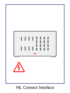
The HIL Connect Interface component, shown in Figure 1, is a signal processing based component from the HIL Interfaces library category. It can be used to send different signals to appropriate outputs of a HIL Connect by choosing a dedicated connector and its pin. Also, it can be used to observe analog and/or digital inputs from the HIL Connect.
Component dialog box and parameters
The HIL Connect component dialog box consists of nine tabs. Tabs "Slots A-H" represent slots on the HIL Connect. Every connector, with its pins, is listed so that you can easily choose if that dedicated pin is used in your hardware setup.
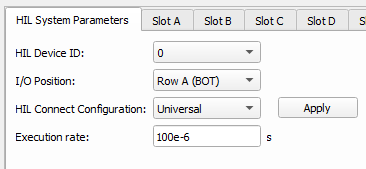
Tab: "HIL System Parameters"
In this component tab, HIL System Parameters of the HIL Connect Interface can be specified.
| Parameter | Name | Description |
|---|---|---|
| HIL Device ID | hil_device_id | This parameter should match the HIL device setting to which the HIL Connect is connected. This is important only in multi-HIL simulations. |
| I\O Position | io_position | This parameter is available only when HIL604 or HIL606 is used. It defines the chosen row - Row A (BOT) or Row B (TOP) for analog and digital I/Os. |
| HIL Connect Configuration | hil_connect_config | Here you can choose between some preset HIL Connect configurations. If
"Specific" is chosen, the "Configuration code" property will appear. Note: To apply a new configuration, you must click the
"Apply" button.
|
| Configuration code | configuration_code | Configuration code describes the cards inside the HIL Connect. This code can
be found on the label on the back of the HIL Connect under CC. By applying a configuration code, the Slot A - Slot H tabs will be configured to match the card and its connectors on the HIL Connect. Note: To apply a new configuration, you must click the
"Apply" button.
|
| Execution rate | execution_rate | Execution rate of the internal signal processing. [s] |
Tabs: "Slot (A-H)"
Each Slot tab manages the configuration of the card in the corresponding Slot, as well as specifying the connector usage for that Slot.
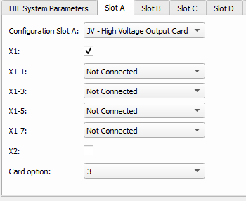
In each tab, there is one constant Configuration Slot parameter, which is used if you want to select code for each slot individually. When the configuration for a slot is chosen, you should press OK in order to apply the changes. When the dialogue is open, under this property you will see properties which correspond to connectors and pins on the HIL Connect.
Table 2 shows cards that are currently supported with this component. You can open documentation for each one of them to see parameters that will appear on the component that correspond to a specific card and a description of ports that will appear on the component.
| Card |
|---|
| Digital Output |
| Digital Input |
| Analog Output |
| Analog Input |
| Current Output |
| High Voltage Output |
| BMS Digital Card |
| BMS Analog Output |
| CAN Resistor Emulator |
| CAN Relay Output Card |
| Fiber Optic Input Card |
| Fiber Optic Output Card |
Some of the cards have options, which better explain some specific cards. Information about the option is represented by a number following the card configuration letters in the configuration code. For example, if JV3 describes the card in Slot E, JV describes that the card is High Voltage Output Card, and 3 is the option. If a card does not have an option, the default value is 0.
HIL Connect Interface ports
When the connector is defined as used, the appropriate signal processing ports appear on the component. For Slots A-D, ports will appear on the left side of the component and for Slots E-H ports will appear on the right side of the component.
Desired output signals can be sent to the HIL Connect through input ports, and signals from the analog and/or digital inputs of the HIL Connect can be accessed through output ports. As internal probes and digital probes already exist, these ports can be used for sourcing signals inside of the model.
Most of the terminals on the component are vectors, where each element of vector corresponds to one pin of connector. For example, if an input port appears for Analog Output Card, a vector of length 8 should be connected to this input. Values of all analog signals fed to the input terminals of this component should be equal to the expected value at the output of the HIL Connect.
More details can be found in documentation related to individual cards.
Equations for scaling, offset, and limits used in the HIL Connect Interface component
The HIL Connect Interface component calculates scaling, offset, and limits for analog outputs considering the given range of the signal in the simulation and the desired range on the output of HIL Connect. Equations are only applied when signal chooser is used to assign the selected signal to the appropriate analog output.
Scaling:
Scaling is calculated by the following equation:
Where:
- Vsimu_max - maximum value of the simulation variable;
- Vsimu_min - minimum value of the simulation variable;
- VHIL_Connect_max – maximum desired voltage/current at the analog output of the HIL Connect (if set to a value that exceeds the hardware upper limit, it will be limited to the hardware limit);
- VHIL_Connect_min – minimum desired voltage/current at the analog output of the HIL Connect (if set to a value that exceeds the hardware lower limit, it will be limited to the hardware limit);
- G – gain of the HIL Connect.
Gain of the HIL Connect is a parameter depending on the hardware of the HIL Connect. It can be calculated using a range (peak value) of output on HIL Connect and the peak value of output of HIL Device. For example, gain for a High Voltage Output Card can be calculated by the following equation:
Where:
- VHIL_Connect_peak - peak value of the analog output, defined by the hardware specification of the HIL Connect;
- VHIL_Device_peak - peak value of the analog output of the HIL device (10 V).
Offset:
Offset is calculated by the following equation using the scaling and gain of the HIL Connect from the previous section:
Where:
- VHIL_Connect_max – maximum desired voltage/current at the analog output of the HIL Connect;
- G – gain of the HIL Connect;
- Vsimu_max - maximum value of the simulation variable;
- scaling.
Lower/Upper Limit
Calculation for the lower and upper limits takes into consideration only the desired range of the output of the HIL Connect, but scaled to the HIL Device range. The following equation describes how the upper limit is calculated (same can be applied for the lower limit, but using the desired lower limit of the HIL Connect):
Where:
- VHIL_Connect_max – maximum desired voltage/current at the analog output of the HIL Connect;
- G – gain of the HIL Connect.