Remote IO Interface (Ethernet)
Description of the Remote IO Interface (Ethernet) component in Schematic Editor.
Remote IO Interface (Ethernet) Description
The Remote IO Interface (Ethernet) component is used to send and receive input/output data from a HIL Remote IO Interface. Communication between the HIL Simulator and the HIL Remote IO Interface is through Ethernet Variable Exchange. This component is a signal processing based component from the HIL Interfaces library category.
Internally this component comprises of two Remote IO Card (Ethernet) units corresponding to the two independent cards inside the Remote IO device, labeled Device ID 1 and Device ID 2 on the back of device.
Component dialog box and parameters
General parameters for the Remote IO Interface (Ethernet) component can be defined in the component properties dialog box.
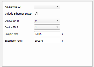
| Parameter | Name | Description |
|---|---|---|
| HIL Device ID | hil_device_id | This parameter should match the HIL device ID number to which the Remote IO
Device is connected. This is important only in multi-HIL simulations. Choose "-"
if only one HIL is used. Note: In Multi-HIL systems, all
Remote IO Interface (Ethernet) components in the Schematic Editor model must be
assigned to the same HIL Device. |
| Include Ethernet Setup | include_eth_setup | Includes an ETH VE Setup component. Only one Remote IO Interface component
can have this checked. Note: If an ETH VE Setup component is used outside of the
Remote IO Interface component, its IP address should be set to
192.168.20.10.
|
| Device ID 1 | device_id1 | Position of rotary switch 2 under the label Device ID 1 on the back of Remote IO Device. |
| Device ID 2 | device_id2 | Position of rotary switch 2 under the label Device ID 2 on the back of Remote
IO Device. Note: Device IDs should be set in ascending order to ensure
proper transmission of data.
|
| Sample time | sample_time | Message sending rate. [s] |
| Execution rate | execution_rate | Execution rate of the internal signal processing. [s] |
Remote IO Interface (Ethernet) ports
There are eight ports which are available for the Remote IO Interface (Ethernet) component, divided in to 2 groups, where each group corresponds to a single card inside of the Remote IO Device. A single group consists of one pair of analog and digital inputs, as well as one pair of analog and digital outputs. Input ports on the left side of the component are used to send appropriate digital and analog outputs to the Remote IO Device. Available inputs are given in Table 2.
Values of all analog signals fed to the input terminals of this component should be equal to the expected value at the output of the Remote IO Device. For example, if an 8 V value is needed at the analog output of the Remote IO, the value of the provided signal in the model should be 8.
Available output ports are given in Table 3. Through these outputs, the signals from the analog and digital inputs of the Remote IO can be accessed. As internal probes and digital probes already exist, these ports can be used for sourcing signals inside of the model.| Port label | Description | Vector length |
|---|---|---|
| AO 1 | Vector input used to assign signals to Analog outputs of the Remote IO Card marked with Device ID 1. Every element of the vector corresponds to one pin on the front plate connector. | 32 |
| DO 1 | Vector input used to assign signals to Digital outputs of the Remote IO Card marked with Device ID 1. Every element of the vector corresponds to one pin on the front plate connector. | 32 |
| AO 2 | Vector input used to assign signals to Analog outputs of the Remote IO Card marked with Device ID 2. Every element of the vector corresponds to one pin on the front plate connector. | 32 |
| DO 2 | Vector input used to assign signals to Digital outputs of the Remote IO Card marked with Device ID 2. Every element of the vector corresponds to one pin on the front plate connector. | 32 |
| Port label | Description | Vector length |
|---|---|---|
| AI 1 | Vector output used to source signals from Analog inputs of the Remote IO Card marked with Device ID 1. Every element of the vector corresponds to one pin on the front plate connector. | 16 |
| DI 1 | Vector output used to source signals from Digital inputs of the Remote IO Card marked with Device ID 1. Every element of the vector corresponds to one pin on the front plate connector. | 32 |
| AI 2 | Vector output used to source signals from Analog inputs of the Remote IO Card marked with Device ID 2. Every element of the vector corresponds to one pin on the front plate connector. | 16 |
| DI 2 | Vector output used to source signals from Digital inputs of the Remote IO Card marked with Device ID 2. Every element of the vector corresponds to one pin on the front plate connector. | 32 |