FRT Container
Description of the Fault Ride Through Container (FRT) component in Schematic Editor
Component Icon
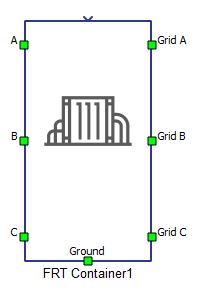
Description
The FRT Container component emulates test equipment used for examining fault ride through behaviour. The component is comprised of a longitudinal (length) impedance and a short-circuit (query) impedance. These impedances are implemented as Variable passive components, whose values are specified through SCADA Input components.
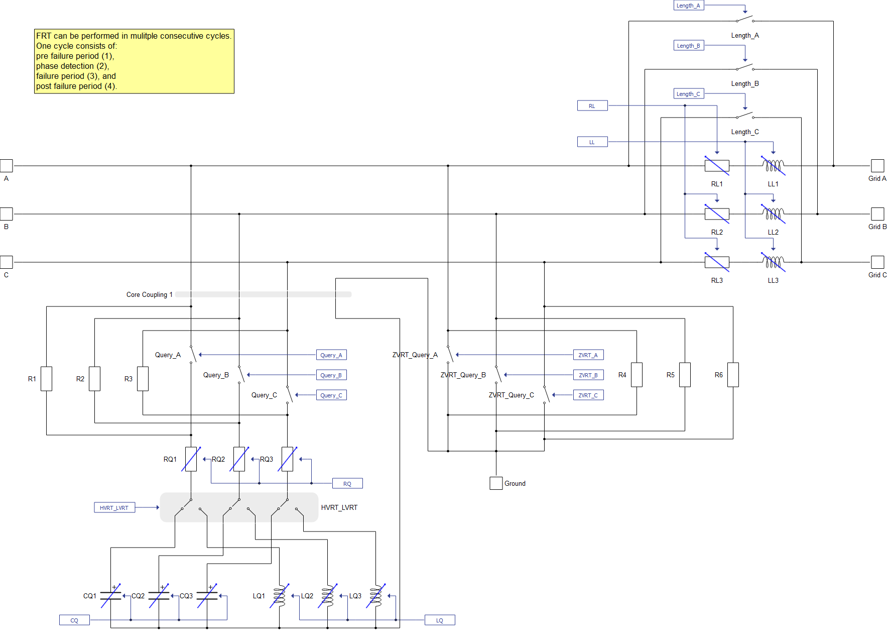
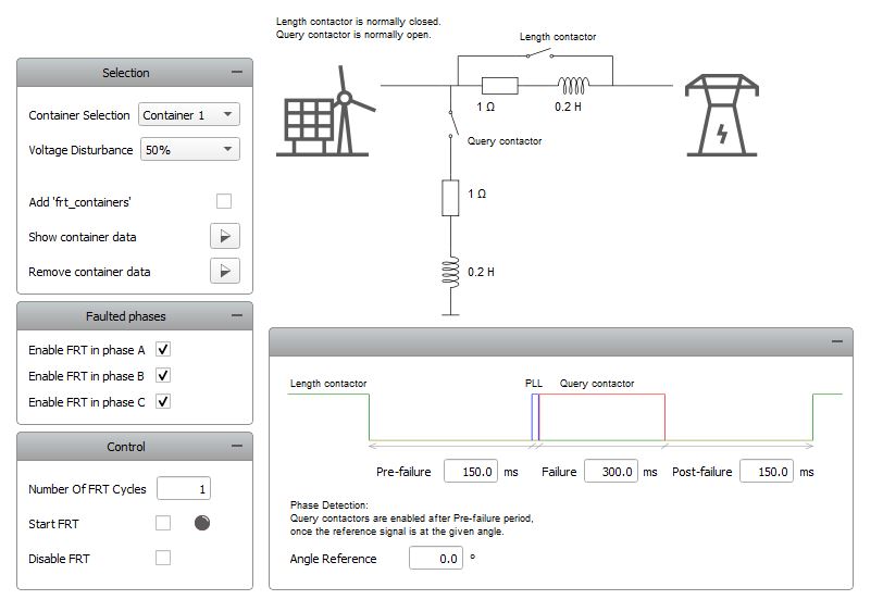
The internal structure of the component is shown in Figure 2. The two sections in the power stage of the component are the length inductive impedance, and the query impedance. The nature of the query impedance depends on the type of simulated voltage ride through; the impedance is capacitive in the high-voltage ride-through (HVRT) case, inductive in the low-voltage ride-through (LVRT) case, and the output terminals are directly short-circuited in the zero-voltage ride-through (ZVRT) case.
When the FRT Container is not in operating mode, both the length and the query impedances are disconnected from the remaining circuit. That is, the length contactors are normally closed, and the query contactors are normally open. During a fault ride through event, the length impedances are connected. One fault ride through period consists of three subperiods: pre-failure, failure, and post-failure. The query impedances are connected only in the failure period.
- Supported types: real
- Vector support: no
Properties
 |
 |
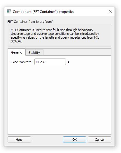
- Execution rate
- Type in the desired signal processing execution rate. This value must be compatible with other signal processing components of the same circuit: the value must be a multiple of the fastest execution rate in the circuit. There can be up to four different execution rates, but they must all be multiple of the basic simulation timestep. To specify the execution rate, you can use either decimal (e.g. 0.001) or exponential values (e.g. 1e-3) in seconds. Alternatively, you can type in ‘inherit’ in which case the component will be assigned execution rate based on the execution rate of the components it is receiving input from.
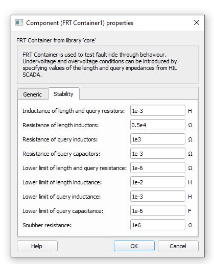
- Inductance of length and query resistors
- The value of parasitic inductances of variable resistors in length and query branches.
- Resistance of length inductors
- The value of parasitic resistances of variable inductors in length branches.
- Resistance of query inductors
- The value of parasitic resistances of variable inductors in query branches.
- Resistance of query capacitors
- The value of parasitic resistances of variable capacitors in query branches.
- Lower limit of length and query resistance
- The lower limit value of resistances of variable resistors in length and query branches.
- Lower limit of length inductance
- The lower limit value of inductances of variable inductors in length branches.
- Lower limit of query inductance
- The lower limit value of inductances of variable inductors in query branches.
- Lower limit of query capacitance
- The lower limit value of capacitances of variable capacitors in query branches.
- Snubber resistance
- The value of resistances of resistive snubbers connected in parallel with single phase switches in query branches.
Variable passive components contain additional resistances and inductances, which are included in order to ensure their stability. These parasitic elements affect the total impedances of length and query branches. Their contribution to the total impedance is taken into account when resistances, inductances, and capacitances of variable components are specified.
FRT Container component SCADA inputs
An overview of user inputs is given in Table 1.
Values of the resistance and reactance of length and query impedances are specified with appropriate SCADA inputs. Once specified, the values can not be updated while a fault ride through cycle is active.
| Input | Description |
|---|---|
| Start | Digital input whose rising edge activates the component. |
| Number of cycles | Analog input which specifies the number of consecutive FRT cycles to simulate. |
| Disable | Digital input which disables activation of the following FRT cycle when the input value is high. |
| RL | Resistance value of length impedances. [Ω] |
| LL | Inductance value of length impedances. [H] |
| RQ | Resistance value of query impedances. [Ω] |
| LQ | Inductance value of query impedances. [H] |
| CQ | Capacitance value of query impedances. [F] |
| Pre-failure period | Duration of the pre-failure period. [ms] |
| Failure period | Duration of the failure period. [ms] |
| Post-failure period | Duration of the post-failure period. [ms] |
| Angle reference | Value of the angle of the reference signal. [°] |
| Voltage disturbance | Value of the expected voltage disturbance, relative to grid voltage. [%] |
| Enable A | Digital input which enables simulation of fault ride through in phase A when the input value is high. |
| Enable B | Digital input which enables simulation of fault ride through in phase B when the input value is high. |
| Enable C | Digital input which enables simulation of fault ride through in phase C when the input value is high. |
A dedicated Library Widget for controlling the FRT Container component is available.
Values of resistances and reactances of length and query branches can be loaded to the Library Widget by checking the Add 'frt_containers' check box. This action loads a variable named frt_containers from the global namespace. Variables can be added to the global namespace by specifying them in the Panel Initialization script. If the parameter values are specified in the frt_containers variable in the code format below, they will be available for selection in the FRT Container Library Widget.
The general structure of the frt_containers variable is as follows:
frt_containers = {
  container name(str): {
  voltage disturbance value: {"RL": RL value, "LL": LL value, "RQ": RQ value, "LQ": LQ value, "CQ": CQ value}}
}
An example of the frt_containers variable specification is as follows:
frt_containers = {
  "My Container 1": {
    33: {"RL": 1, "LL": 0.2, "RQ": 1, "LQ": 0.1, "CQ": 0},
    50: {"RL": 0.8, "LL": 0.01, "RQ": 0.8, "LQ": 0.01, "CQ": 0}
  },
  "My Container 2": {
    50: {"RL": 0.5, "LL": 0.02, "RQ": 0.5, "LQ": 0.02, "CQ": 0},
   135: {"RL": 1, "LL": 0.22, "RQ": 1, "LQ": 0, "CQ": 12e-6}
  }
}