Output Voltage Comparator
This reference section describes the Output Voltage Comparator Signal.
Output Voltage Comparator overview
The Output Voltage Comparator is a digital signal that indicates the voltage level at the output of an inverter leg. It is available in a HIL Device's Digital Signal list and is updated in every digital input sampling cycle when assigned to a digital output. It is supported for Half Bridge and Three Phase Inverter components.
For a Two Level Voltage Source Inverter Leg, the Output Voltage Comparator signal is high when the voltage from Figure 1 is greater than . Otherwise, the signal is low.
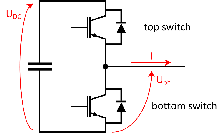
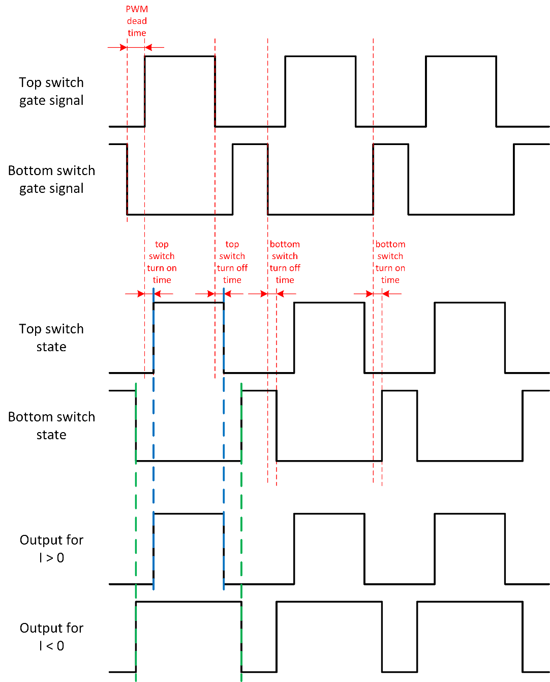
The Output Voltage Comparator's value is determined considering the values of control inputs controlling the switches, the switching delay, the sign of the output current I and the input Udc and the output voltage Uph. This is represented in Figure 2 as a figure, and in Table 1, in a tabular form.
| top switch state | bottom switch state | current sign | output voltage comparator |
|---|---|---|---|
| 0 | 0 | -1 | 1 |
| 0 | 0 | 0 | |
| 0 | 0 | 1 | 0 |
| 0 | 1 | X | 0 |
| 1 | 0 | X | 1 |
| 1 | 1 | X | 1* |
* DTV Flag active.
- current sign = -1 if I < 0
- current sign = 0 if I = 0
- current sign = 1 if I > 0.
Three phase inverter pull-up mode
In cases when Vout comparator pull-up mode is selected in the Three Phase Inverter component, the output voltage comparator logic is slightly modified. During inverter coasting (all switch control inputs on all three phases are inactive), output voltage comparator signals on all three phases are forced to 1. In all other operating modes, output values are defined by the truth table shown in Table 1.
Two mode operation
In order to minimize output latency, the output voltage comparator logic works in two distinct operating modes: active and coasting. The Vout comparator timeout property in the Three Phase Inverter component defines the time period that both GDS input signals in the given phase leg must remain at zero until the logic automatically switches into coasting mode. For optimal performance, the timeout should be set to a value that is slightly higher than the maximum expected dead time.