Parallel Converter DTV Detector
Description of the Parallel Converter DTV Detector component in Schematic Editor
Description
The Parallel DTV detector component configures a dedicated hardware unit of the same name, which detects shoot-through conditions between two or more converters connected in parallel. This hardware unit operates independently and simultaneously with the single converter DTV logic, and the parallel DTV conditions are reported using the standard DTV flag available in both HIL SCADA and HIL API.
When dealing with converters in parallel, shoot-through conditions can happen between the legs of the parallel converters, even if there are no destructive switching states in a particular leg.
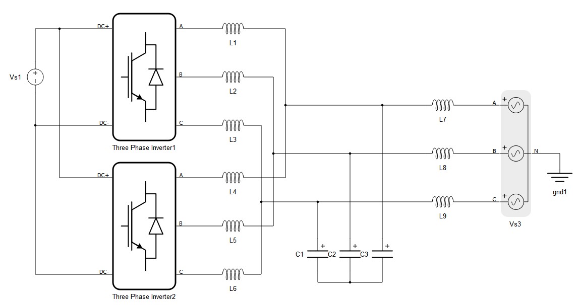
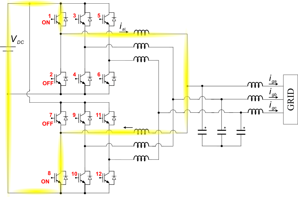
To illustrate that, consider the interleaved grid-connected converter shown in Figure 2, comprising a pair of two-level three-phase inverters in parallel. In this case, there is a total of 12 switches arranged in 6 legs, with two parallel legs per phase. This example topology is better detailed in Figure 3.
Note that, even if all legs operate with complimentary switching states, a shoot-through condition can be established by the parallel connection between the converters. For example, Figure 3 illustrates the case where a low impedance path across the power supply is created by turning on the switches 1 and 8 at the same time.
To be able to detect such undesirable conditions, you can use the Parallel Converter DTV detector component, which supports the same topologies as the standard DTV detector.
The parallel converter DTV detector component is functionally based on the single converter DTV detection function. For the interleaved convert shown above, a simplified block diagram of the component is illustrated in Figure 4, considering the parallel legs connected to phase A.
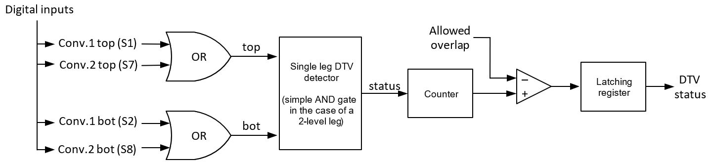
Notice that the Parallel DTV detector component also offers the option to tolerate a configurable overlap period between the converter legs (Allowed overlap). The overlap period detection logic operates with the digital input resolution, and the maximum supported overlap is 5 μs.
The parallel DTV detector component is currently supported by Typhoon HIL604, HIL506, and HIL606 devices. Each component can handle up to 4 parallel legs and you can use up to 3 components per device, which means that 4 parallel 3-phase converters are supported per device. Multi HIL operation is also supported.
Component dialogue box and parameters
The Parallel converter DTV detector component dialogue box consists of 2 tabs.
Tab: "General"
In this tab, you can define the configuration of the parallel converter DTV detector component. For instance, for the topology shown in Figure 2, the configuration is illustrated in Figure 5.
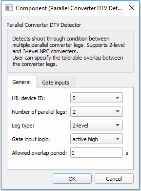
Parallel converter DTV detector "General" parameters
| Parameter | Code name | Description |
|---|---|---|
| HIL device ID | hil_device_id | Defines location of the DTV detector block in case of a multi device setup. |
| Number of parallel legs | leg_num | Number of parallel converter legs, up to 4 supported. |
| Leg type | leg_type | Leg type selector. |
| Gate input logic | gate_input_logic | Gate input logic, common for all the inputs. |
| Allowed overlap period | allowed_overlap | Allowed overlap period between the legs in seconds. Resolution is as high as 6.25 ns for HIL402, 602+, and 604 devices, 4.5 ns for HIL101 devices, and 3.5 ns for HIL404, HIL506, and HIL606 devices. |
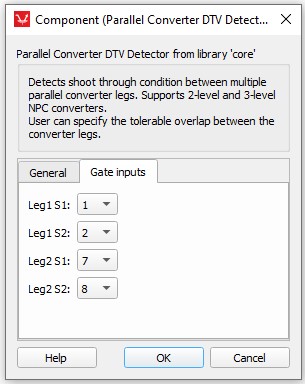
Tab: "Gate inputs"
In this tab, you can assign the digital inputs to the parallel converter DTV detector components. The number of inputs varies with the Number of parallel legs and Leg type parameters. For the topology shown in Figure 2, three detector components can be used, one for each phase. The configuration of the detector component relative to the legs connected to phase A is illustrated in Figure 6. The same reasoning is valid for phases B and C and their respective detector components.