DTV detection
This reference section describes the Dead Time Violation (DTV) detecting function used in multiple converter components.
The goal of the DTV detection function is to detect and report destructive switching states of the simulated converter blocks. DTV detection block operates on converter control inputs and runs at the digital input sampling resolution (as high as 6.25 ns for HIL402, 602+, and 604 devices, 4.5 ns for HIL101 devices, and 3.5 ns for HIL404, HIL506, and HIL606 devices). It supports standard 2-level and 3-level NPC topologies.
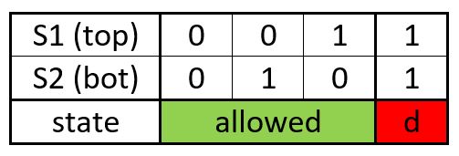
In 2-level mode, DTV is reported only when both switches in a leg are active. In combination with switching delay function it can also be used to precisely detect minimum dead time period duration or even allow certain signal overlapping.

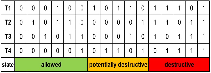
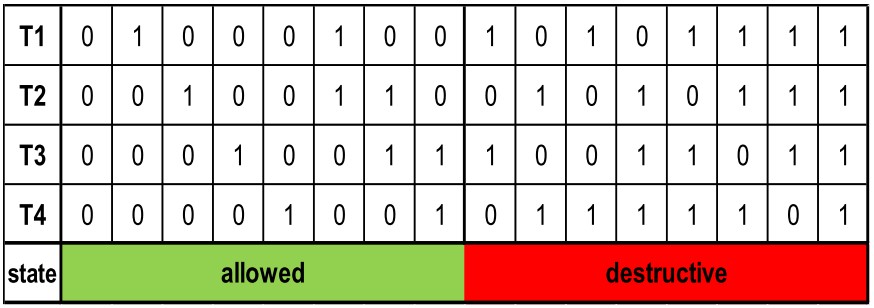
In case of 3-level converters, DTV logic is based on the Semikron Application Note AN-11001 where only destructive states are reported.

