Providing absolute machine encoder position over a standardized protocol
This section describes the machine capability to provide absolute encoder position data.
Overview
Absolute encoders are capable of providing a unique machine rotor position and a number of machine rotor revolutions. The output of a singleturn absolute encoder indicates the current shaft position, making it an angle transducer. The output of a multiturn absolute encoder indicates the current number of machine rotor revolutions.
Machines running on a HIL device can send encoder data to external devices using EnDat, BiSS, or SSI standardized protocols.
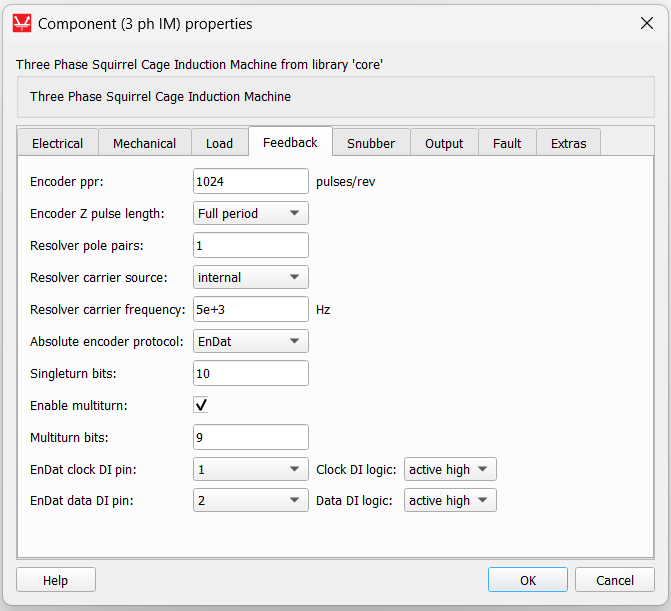
Singleturn absolute encoder resolution is defined by the Encoder ppr property on the Feedback tab of the selected machine's component properties dialog. In order to transmit complete machine rotor position information via chosen absolute encoder protocol, the following condition must be satisfied:
where n is the number of singleturn bits. If the assigned Encoder ppr value is greater than 2n, information about the machine rotor position sent through the singleturn encoder will be incomplete and will result in an error. If the Encoder ppr value is less than 2n, a certain number of the MSBs of the singleturn absolute encoder will be zeroed.
If the Enable multiturn property is checked, you can specify a number of multiturn bits for providing information about the current number of machine rotor revolutions. When one full revolution of the machine rotor is made, the multiturn counter will be increased.
Protocol limitations
Implemented protocol limitations are:
- General:
- Binary encoding
- No CRC
- EnDat:
- Only the Encoder send position values command is supported (code 000111). This EnDat 2.1 command is compatible with EnDat2.2
- Position values are sampled with interrupted clock
- BiSS:
- Only point-to-point configuration is supported
- Only Single Cycle Data (SCD) is supported
- Right-aligned
- SSI:
- Only point-to-point configuration is supported
Digital input configuration
Clock and data signals from an external device should be connected to the desired digital input pin on the HIL device. These pins need to be defined in the machine dialog window. On the Feedback tab, values for clock and data pins need to be defined. The connected signal can be active high, or active low, depending on the connected external device.
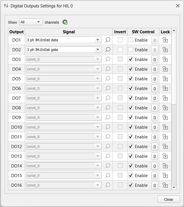
Digital output configuration
Data from the HIL device (machine_name.EnDat data, machine_name.EnDat gate, machine_name.BiSS data and machine_name.SSI data) can be set to any digital output. Digital outputs are defined in the Digital Outputs window in HIL SCADA (Figure 2).