Transmission Line
Description of the Transmission Line component in Schematic Editor


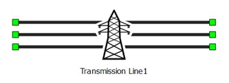
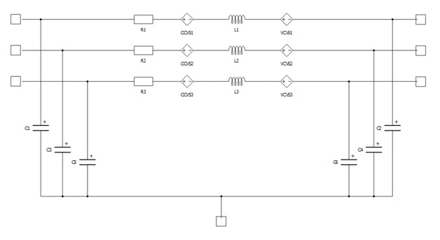
This component models a transmission power line. Component parameters can be defined in three ways depending on the value of the Model definition parameter. If Model definition is set to Geometry, parameters depend on the geometric arrangement of transmission line conductors and geometric properties of individual conductors. Positions and geometric properties of individual conductors are user defined.
If Model definition is set to RLC, transmission line R, L, and C parameters are defined by the user as per length matrices in the phase domain. Phase domain parameters are defined as nested python lists [[L11, L12, L13], [L21, L22, L23], [L31, L32, L33]], where diagonal elements represent self-inductances of each phase, and off-diagonal elements represent mutual coupling inductances between phases. Number of elements in the nested lists are defined by the Number of phases parameter.
If Model definition is set to Sequence, transmission line R, L, and C parameters are defined by the user as per length matrices in the sequence domain. Sequence domain parameters are defines as nested python lists [[L00, L0d, L0i], [Ld0, Ldd, Ldi], [Li0, Lid, Lii]], where diagonal elements represent inductances of zero, positive and negative sequence respectively. Sequence model is defined only if Number of phases is set to three.
Ports
- a_in
- Transmission line phase A input port
- b_in
- Available if Number of phases is set to 2, 3, or 4
- Transmission line phase B input port
- c_in
- Available if Number of phases is set to 3 or 4
- Transmission line phase C input port
- d_in
- Available if Number of phases is set to 4
- Transmission line phase D input port
- a_out
- Transmission line phase A output port
- b_out
- Available if Number of phases is set to 2, 3, or 4
- Transmission line phase B output port
- c_out
- Available if Number of phases is set to 3 or 4
- Transmission line phase C output port
- d_out
- Available if Number of phases is set to 4
- Transmission line phase D output port
- gnd
- Available if Model is set to PI
- Transmission line ground port
Properties
- Model
- Type of model used to represent the transmission line
- Available values are RL coupled and PI
- Number of phases
- Number of phases in the transmission line
- Available values are 1, 2, 3, or 4
- Model definition
- Type of transmission line parameters definition
- Available values are Geometry, RLC, and Sequence
- Sequence model definition is available only if Number of phases is set to three
-
Unit system
- Unit system of the component
- Available values are metric and imperial
- Length
- Transmission line length
- Units are in km if Unit system is set to metric, or in miles if Unit system is set to imperial
- Frequency
- Available if Model definition is set to Geometry or Sequence
- Transmission line operating frequency [Hz]
- Earth resistivity
- Available if Model definition is set to Geometry
- Value of Earth resistivity [Ωm]
-
CCx
- Available if Model definition is set to Geometry
- Horizontal distance from a cable to a chosen reference
- Units are in metres if Unit system is set to metric, or in feet if Unit system is set to imperial
- Property value needs to be set for all conductors, depending on the Number of phases parameter
-
CCy
- Available if Model definition is set to Geometry
- Vertical distance from a cable to the ground
- Units are in metres if Unit system is set to metric, or in feet if Unit system is set to imperial
- Property value needs to be set for all conductors, depending on the Number of phases parameter
-
GMR
- Available if Model definition is set to Geometry
- Geometric mean radius of the cable
- Units are in metres if Unit system is set to metric, or in feet if Unit system is set to imperial
- Property value needs to be set for all conductors, depending on the Number of phases parameter
-
RD
- Available if Model definition is set to Geometry
- Radius of the conductor
- Units are in metres if Unit system is set to metric, or in feet if Unit system is set to imperial
- Property value needs to be set for all conductors, depending on the Number of phases parameter
-
Rs
- Available if Model definition is set to Geometry
- Conductor's resistence
- Units are in Ω/km if Unit system is set to metric, or in Ω/mile if Unit system is set to imperial
- Property value needs to be set for all conductors, depending on the Number of phases parameter
-
R
- Available if Model definition is set to RLC
- Transmission line resistance matrix
- Dimensions of the matrix are n x n, where n is the number of phases defined with Number of phases
- Units are in Ω/km if Unit system is set to metric, or in Ω/mile if Unit system is set to imperial
-
L
- Available if Model definition is set to RLC
- Transmission line inductance matrix
- Dimensions of the matrix are n x n, where n is the number of phases defined with Number of phases
- Units are in H/km if Unit system is set to metric, or in H/mile if Unit system is set to imperial
-
C
- Available if Model definition is set to RLC and Model is set to PI
- Transmission line capacitance matrix
- Dimensions of the matrix are n x n, where n is the number of phases defined with Number of phases
- Units are in F/km if Unit system is set to metric, or in F/mile if Unit system is set to imperial
-
Sequence R
- Available if Model definition is set to Sequence and Number of phases is set to three
- Transmission line resistance matrix in the sequence domain
- Dimensions of the matrix are 3 x 3
- Units are in Ω/km if Unit system is set to metric, or in Ω/mile if Unit system is set to imperial
-
Sequence L
- Available if Model definition is set to Sequence and Number of phases is set to three
- Transmission line inductance matrix in the sequence domain
- Dimensions of the matrix are 3 x 3
- Units are in H/km if Unit system is set to metric, or in H/mile if Unit system is set to imperial
-
Sequence C
- Available if Model definition is set to Sequence, Number of phases is set to three, and Model is set to PI
- Transmission line capacitance matrix in the sequence domain
- Dimensions of the matrix are 3 x 3
- Units are in F/km if Unit system is set to metric, or in F/mile if Unit system is set to imperial
Coupling (Tab)
- TLM Embedded coupling type will be replaced with a corresponding inductor in TyphoonSim.
- Embedded TLM coupling
- Available if Number of phases is 2, 3, or 4
- Enables or disables embedded TLM coupling
- If enabled, Transmission line inductance will be split between TLM and component inductors
- TLM/Embedded componenets ratio
- Available if Number of phases is 2, 3, or 4
- Specifies how the ratio between TLM and component inductance will be calculated
- The available option is Manual, allowing the ratio to be chosen manually
- Ratio
- Available if Number of phases is 2, 3, or 4
- Ratio between TLM and Transmission line inductance