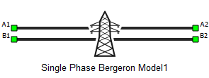
Single Phase Bergeron Model
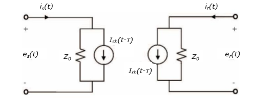
This section describes a Bergeron single phase transmission line based on a distributed parameter traveling wave model with lumped resistance.


This model represents the L and C elements in a distributed manner while resistance R is lumped. In the case when line is lossless( r = 0), model is characterized by two values: the wave propagation speed and the characteristic impedance .
Transport delay is , where d is the length of the line and v is the propagation speed.
It is important to note that transport delay value must be greater than execution rate.
The model equations are:
math
And two current sources are:
This set of equations can be implemented for time discrete modelling of the line if the transport delay, τ, is integer multiple of the simulation step, T , or can be approximated as such: τ = NT.
For lossy lines, total resistance is lumped, at each end and in the middle of the line. When losses are taken into account, equations are obtained as:
where:
Ports
- A1
- Bergeron transmission line A1 port
- B1
- Bergeron transmission line B1 port
- A2
- Bergeron transmission line A2 port
- B2
- Bergeron transmission line B2 port
Properties
- Unit system
- Visible if Model definition is set to R-L
- Specifies if metric or imperial unit system is used for parameter definition
- Available properties are metric and imperial
- Length
- Transmission line length
- Units are in km if Unit system is set to metric, or in miles if Unit system is set to imperial
- Resistance per unit length
- Transmission line resistance per unit length
- Units are in Ω/km if Unit system is set to metric, or in Ω/miles if Unit system is set to imperial
- Core capacitance per unit length
- Cable core capacitance per unit length
- Units are in F/km if Unit system is set to metric, or in F/miles if Unit system is set to imperial
- Shield capacitance per unit length
- Cable shield capacitance per unit length
- Units are in F/km if Unit system is set to metric, or in F/miles if Unit system is set to imperial
- Inductance per unit length
- Cable inductance per unit length
- Units are in H/km if Unit system is set to metric, or in H/miles if Unit system is set to imperial
- Execution rate
- Execution rate of the component
References
[1] Dommel, H., “Digital Computer Solution of Electromagnetic Transients in Single and Multiple Networks,” IEEE® Transactions on Power Apparatus and Systems, Vol. PAS-88, No. 4, April, 1969.