RL section
Description of the RL Section component in Schematic Editor

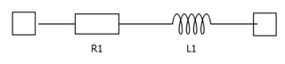
RL Section is a simplified model of an overhead or underground transmission line without phase coupling considerations. RL section parameters can be defined in two ways. If the R-L model definition is selected, the cable length and the per length resistance and inductance must be defined. If the S-U model definition is chosen, the maximal complex power that is expected through the line, voltage, and frequency must be defined. The section resistance and inductance are then approximated by assuming a 10% voltage drop over the section impedance.
Ports
- Px
- RL section Px terminal
- x is the phase number which depends on the Number of phases parameter
- Number of ports depends on Number of phases parameter
- Py
- RL section Py terminal
- y is the phase number which depends on the Number of phases parameter
- Number of ports depends on Number of phases parameter
General (Tab)
- Model definition
- Component parameters definition type
- Available properties are R-L and S-U
- Unit system
- Visible if Model definition is set to R-L
- Specifies if metric or imperial unit system is used for parameter definition
- Available properties are metric and imperial
- Number of phases
- Number of phases in the RL section component
- Available values are 1, 2, 3, 4 or 5
- Resistance per kilometer
- Available if Model definition is set to R-L and Unit system is set to metric
- Section resistance per kilometer [Ω/km]
- Resistance per mile
- Available if Model definition is set to R-L and Unit system is set to imperial
- Section resistance per mile [Ω/mile]
- Inductance per kilometer
- Available if Model definition is set to R-L and Unit system is set to metric
- Section inductance per kilometer [H/km]
- Inductance per mile
- Available if Model definition is set to R-L and Unit system is set to imperial
- Section inductance per mile [H/mile]
- Cable length
- Available if Model definition is set to R-L
- Length of the RL section
- Property value can be in kilometers if Unit system is set to metric, or in miles if Unit system is set to imperial
-
Apparent power
- Available if Model definition is set to S-U
- Maximal apparent power of the RL section [kVA]
-
Voltage
- Available if Model definition is set to S-U
- Nominal voltage of the RL section [kV]
- Frequency
- Available if Model definition is set to S-U
- Nominal frequency of the component [Hz]
Coupling (Tab)
- TLM Embedded coupling type will be replaced with a corresponding inductor in TyphoonSim.
- Embedded TLM coupling
- Available if Number of phases is 2, 3, or 4
- Enables or disables embedded TLM coupling
- If enabled, RL section inductance will be split between TLM and component inductors
- TLM/Embedded componenets ratio
- Available if Number of phases is 2, 3, or 4
- Specifies how the ratio between TLM and component inductance will be calculated
- Available properties are Automatic and Manual
- If set to Automatic, ratio will be determined by the discretization method
- If set to Manual, ratio can be chosen manually
- Ratio
- Available if Number of phases is 2, 3, or 4 and TLM/Embedded componenets ratio is set to Manual
- Ratio between TLM and RL section inductance