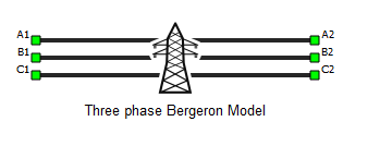
Three Phase Bergeron Model
This section describes a Bergeron three phase transmission line based on a distributed parameter traveling wave model with lumped resistance.


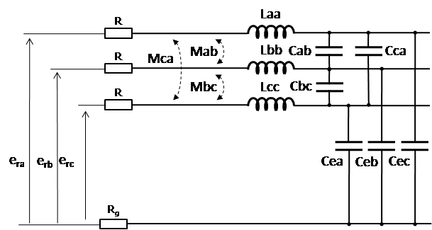
In case of a balanced line , the mathematical model of the circuit can be written in the matrix form:
where matrices [ L ] and [ C ] are:
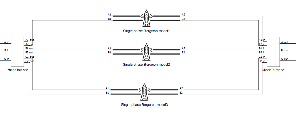
The model of the three phase system is transformed into three decoupled single phase line models, so called "modal" lines, where the transform matrix is: and the inverse transform matrix is
To transform matrices [ L ] and [ C ] into the modal domain, we use the transform matrix:
For each single phase modal line, travel time can be found and a simulation time step, T, selected according to them (Note: in a discrete system, simulation adjusted time steps can only be integer multiples of T).
The calculations previously done in Single phase Bergeron line are made in the modal domain before being converted back to phase values.
Representation of the lossless three phase power line can be expanded to model losses by adding series conductors' resistances and ground resistance.
To transform [ R ] into the modal domain:
Ports
- A1
- Bergeron transmission line phase A port 1
- A2
- Bergeron transmission line phase A port 2
- B1
- Bergeron transmission line phase B port 1
- B2
- Bergeron transmission line phase B port 2
- C1
- Bergeron transmission line phase C port 1
- C2
- Bergeron transmission line phase C port 2
Properties
- Unit system
- Visible if Model definition is set to R-L
- Specifies if metric or imperial unit system is used for parameter definition
- Available properties are metric and imperial
- Length
- Transmission line length
- Units are in km if Unit system is set to metric, or in miles if Unit system is set to imperial
- Resistance per unit length
- Transmission line resistance per unit length
- Units are in Ω/km if Unit system is set to metric, or in Ω/miles if Unit system is set to imperial
- Ground resistance per unit length
- Transmission line ground resistance per unit length
- Units are in Ω/km if Unit system is set to metric, or in Ω/miles if Unit system is set to imperial
- Core capacitance per unit length
- Cable core capacitance per unit length
- Units are in F/km if Unit system is set to metric, or in F/miles if Unit system is set to imperial
- Shield capacitance per unit length
- Cable shield capacitance per unit length
- Units are in F/km if Unit system is set to metric, or in F/miles if Unit system is set to imperial
- Inductance per unit length
- Cable inductance per unit length
- Units are in H/km if Unit system is set to metric, or in H/miles if Unit system is set to imperial
- Execution rate
- Execution rate of the component
References
[1] Dommel, H., “Digital Computer Solution of Electromagnetic Transients in Single and Multiple Networks,” IEEE® Transactions on Power Apparatus and Systems, Vol. PAS-88, No. 4, April, 1969.