Three-Phase Meter
Description of the Three-phase Meter component, which measures currents and voltages of a three-phase system.
The three-phase meter is a component is located in the Microgrid Library. The component's icon and properties window are shown in Table 1. The three-phase meter measures currents and voltages of three-phase system. It outputs the measured values through signal processing output. The output is a fixed size vectorized output. Within the properties window of the meter, different measurements can be enabled/disabled. It is recommended to enable only the measurements that are really required in order to save computational resources. Outputs that are not selected will be automatically set to zero.
| component | component dialog window | component parameters |
|---|---|---|
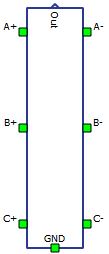 Three-Phase Meter |
 |
|
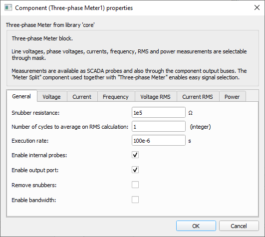
Tab: "General"
In this tab, the snubber resistance, number of cycles to average on RMS calculations and execution rate can be set. It is also possible to enable internal probes, enable output port, remove the snubbers and enable/set bandwidth.
| Parameter | Code name | Description |
|---|---|---|
| Snubber resistance | R | Snubber resistance value. Snubber resistors are connected in parallel to the phase voltage measurements. [Ω] |
| Number of cycles to average on RMS calculation | n_cycles | Number of cycles to use when calculating RMS. This results in an RMS measurement average over "n_cycles". [Integer] |
| Execution rate | Ts | Execution rate of the inner signal processing components. [s] |
| Enable internal probes | enable_probes | Checkbox that enables the placement of probes for the enabled measurements. Set as True by default. |
| Enable output port | enable_out | Checkbox that enables the regular output port. Set as True by default. |
| Remove snubbers | remove_snubber | Checkbox that removes the resistive snubbers from the meter circuit. When set to
True, the property Snubber resistance is disabled. Set as False by default.
WARNING: When this property is set to True, the user must connect the ground port to a valid reference, otherwise measurements will be compromised. |
| Enable bandwidth | enable_bandwidth | Checkbox that enables the bandwidth setting for instantaneous voltage and current measurements.. When set to True, the property Bandwidth is shown and enabled. Set as False by default. |
| Bandwidth | bandwidth | Bandwidth of the low pass filter of the instantaneous voltage and current measurements. This property is hidden by default. [Hz] |
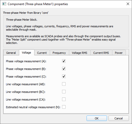
Tab: "Voltage"
In this properties tab, the phase, line and neutral instantaneous voltage measurements can be enabled.
| Parameter | Code name | Description |
|---|---|---|
| Phase voltage measurement (A) | VAn | Checkbox that enables the measurement of phase A's instantaneous voltage |
| Phase voltage measurement (B) | VBn | Checkbox that enables the measurement of phase B's instantaneous voltage |
| Phase voltage measurement (C) | VCn | Checkbox that enables the measurement of phase C's instantaneous voltage |
| Line voltage measurement (AB) | VAB | Checkbox that enables the measurement of A-B line's instantaneous voltage |
| Line voltage measurement (BC) | VBC | Checkbox that enables the measurement of B-C line's instantaneous voltage |
| Line voltage measurement (CA) | VCA | Checkbox that enables the measurement of C-A line's instantaneous voltage |
| Estimated neutral voltage measurement (N) | VN | Checkbox that enables the instantaneous neutral voltage estimation by summing the line-to-neutral three-phase voltages. |
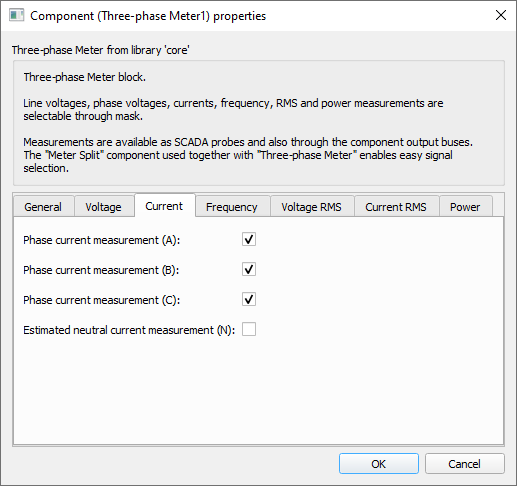
Tab: "Current"
In this properties tab, the phase and neutral instantaneous current measurements can be enabled.
| Parameter | Code name | Description |
|---|---|---|
| Phase current measurement (A) | IA | Checkbox that enables the measurement of phase A's instantaneous current |
| Phase current measurement (B) | IB | Checkbox that enables the measurement of phase B's instantaneous current |
| Phase current measurement (C) | IC | Checkbox that enables the measurement of phase C's instantaneous current |
| Estimated neutral current measurement (N) | IN | Checkbox that enables the instantaneous neutral current estimation by summing the three-phase currents. |
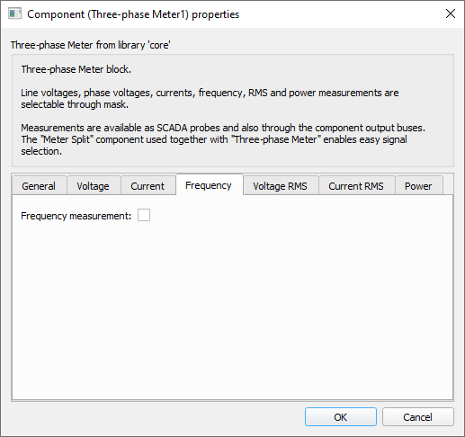
Tab: "Frequency"
In this property tab, the frequency measurement can be enabled. The frequency is measured using a PLL block.
| Parameter | Code name | Description |
|---|---|---|
| Frequency measurement | freq | Checkbox that enables the frequency measurement using a three-phase PLL component |
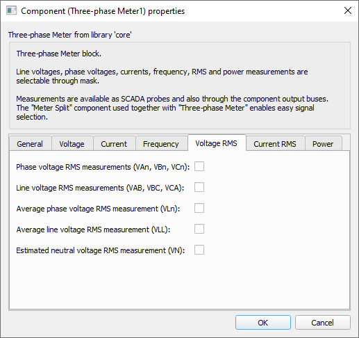
Tab: "Voltage RMS"
In this properties tab, the phase, line and neutral RMS voltage measurements can be enabled.
| Parameter | Code name | Description |
|---|---|---|
| Phase voltage measurements (VAn, VBn, VCn) | VLn_rms | Checkbox that enables the RMS measurements of the three-phase phase voltages (VAn, VBn and VCn). |
| Line voltage measurement (VAB, VBC, VCA) | VLL_rms | Checkbox that enables the RMS measurements of the three-phase line voltages (VAB, VBC and VCA) |
| Average phase voltage RMS measurement (VLn) | VLn_avg_rms | Checkbox that enables the average RMS measurement of the three-phase phase voltages. |
| Average line voltage RMS measurement (VLL) | VLL_avg_rms | Checkbox that enables the average RMS measurement of the three-phase line voltages. |
| Estimated neutral voltage RMS measurement (VN) | VN_rms | Checkbox that enables the RMS measurement of the estimated neutral voltage. |
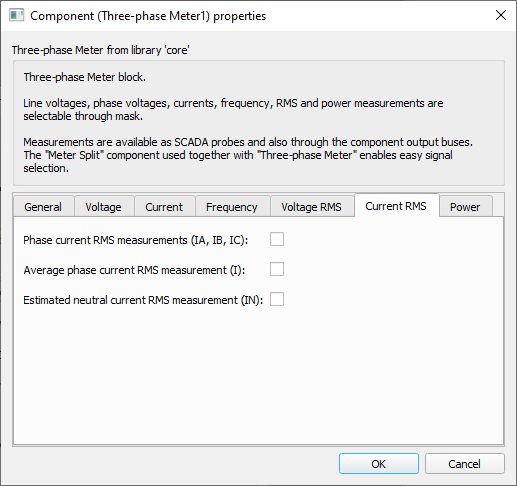
Tab: "Current RMS"
In this properties tab, the phase and neutral RMS current measurements can be enabled.
| Parameter | Code name | Description |
|---|---|---|
| Phase current RMS measurements (IA, IB, IC) | I_rms | Checkbox that enables the RMS measurement of the three-phase phase currents (IA, IB, and IC) |
| Average phase current RMS measurement (I) | I_avg_rms | Checkbox that enables the average RMS measurement of the three-phase phase currents. |
| Estimated neutral current RMS measurement (IN) | IN_rms | Checkbox that enables the RMS measurement of the estimated neutral current. |
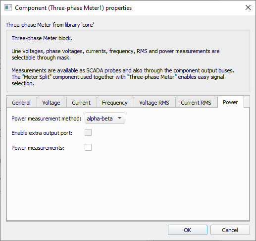
Tab: "Power"
In this properties tab, the power method can be selected, and the power measurement and the extra output port can be enabled.
| Parameter | Code name | Description |
|---|---|---|
| Power measurement method | P_method |
Combo box that enables the selection between two different power measurement methods.
|
| Enable extra output port | enable_extra_out | Checkbox that enables an extra output port. This checkbox is only enabled when the Power measurement method is set to RMS based. The extra output port only contains per-phase power information. |
| Power measurement | P_meas | Checkbox that enables the power measurement according to the Power measurement method chosen. |
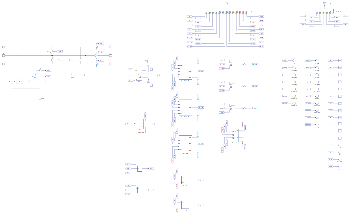
Example
Overall behavior can be better understood with the use of the given three-phase meter example:
Model name: meter_and_const_z_load.tse
SCADA interface: SCADA_Panel.cus
Path: /examples/models/microgrid/meter_and_constant_z_load/