Voltage and Current Measurements
Description of the voltage and current measurement components in Schematic Editor
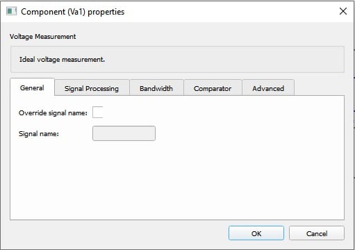
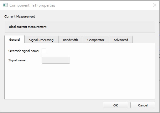
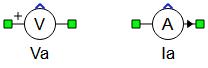
The Current measurement and Voltage measurement components enable you to measure and route the analog output channels with any voltage and current from a modeled circuit. The name of the output variable will correspond to the name given to the component.
| component | component dialog window | component parameters |
|---|---|---|

Voltage measurement |
 |
|

Current measurement |
 |
|
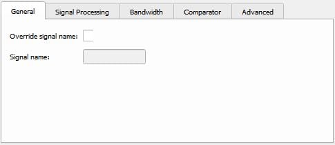
Tab: General
If the Override signal name property checkbox is checked, the Signal name property (which appears in SCADA as the name of the corresponding measurement) can be modified in the appropriate textbox.
Generally, the name of the signal is the name of the component in the model. If it is a part of a subsystem (e.g. Sub1), then the signal's name consists of both the subsystem's and the component's names (Sub1.Measurement1). In the case of nested subsystems, all appear in the signal's name (e.g. Sub1.Sub2.Sub3.Measurement1).
Overriding the signal name both modifies the desired signal's name, and can mask the appearance of subsystems being mentioned in the name of the signal. Table 2 shows a few examples to demonstrate this for the hypothetical component s1.s2.s3.Va1.
| Textbox entry | Signal name in SCADA |
|---|---|
| signal1 | signal1 |
| .signal1 | s1.s2.s3.signal1 |
| ..signal1 | s1.s2.signal1 |
| .s4.signal1 | s1.s2.s3.s4.signal1 |
| ..s4.signal1 | s1.s2.s4.signal1 |
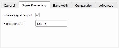
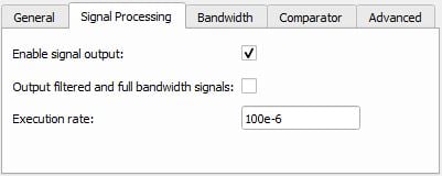
Tab: Signal Processing
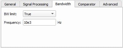
Tab: Bandwidth
In order to emulate the bandwidth of some real sensors, a first order filter can be used with measurement blocks. The first order filter is activated by setting BW limit to True in the Bandwidth tab, in each measurement components' Properties window. The cutoff frequency is defined as the frequency where the gain filter is -3 dB. An RC filter is used for voltage filtering, while an RL filter is used for current filtering, as shown in Figure 6. The name of the filtered voltage/current is the user defined label of the measurement. The not filtered voltage/current is also available under name: (user defined label)_not_filtered.
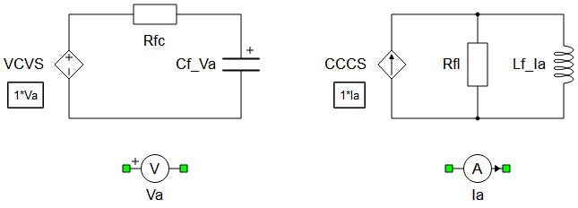
Resistor and capacitor values shown in Figure 6 are calculated as:
The resistor and inductor in LR filter are calculated as:
Where fc is a cutoff frequency set by the user.
Tab: Comparator
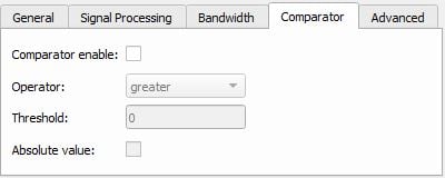
An additional feature of the measurement blocks is comparator functionality. The Comparator tab in the measurement block properties window is shown in Figure 7. It is the same for both the Current Measurement and Voltage Measurement components.
The comparator feature is activated by checking the Comparator enable property checkbox. The operator for comparison can be set in one of five different modes: equal; greater; less; greater or equal; less or equal. A threshold value can be set in the Threshold text box. There is a option to compare the threshold with the absolute value of the signal, which can be activated by checking the parameter Absolute value. This option is usually used when the comparator input is an AC signal. The comparator output can be observed from the digital outputs. In the Control Panel Digital Output settings, a comparator output will appear as (user defined name for measurement)_cmp.
Analog output signals from measurements added in the schematic
| Analog output variable name | Description |
|---|---|
| name | Regular output from measurement or filtered if bandwidth limit is enabled |
| name_full_bandwidth | Regular output from measurement if bandwidth limit is enabled |
Digital output signals from current and voltage measurements
| Digital output variable name | Description |
|---|---|
| name_cmp | Output from the compare unit, if enabled |
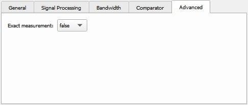
Tab: Advanced
- Latency of the measured signal is one simulation step less,
- Measurement accuracy is increased (this might be important if the system have very fast time constants <1e-5s).
- Might increase the memory usage,
- Might require more processing power which may result in a larger required simulation step.