Ideal
This section describes single- and double-throw contactors modeled as ideal switches.
The Schematic Editor core library includes 1-, 2-, 3-phase single and double throw contactors which are shown in Table 1. Contactors are modeled with ideal switches (zero on resistance and infinite off resistance) that instantaneously change state upon control input signal change.
| component | component dialog window | component parameters |
|---|---|---|
|
SPST contactor DPST contactor TPST contactor 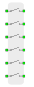 MPST contactor |
  |
|
|
SPDT contactor DPDT contactor TPDT contactor |
Contactor properties are described in Table 2.
| Group | Name | Description |
|---|---|---|
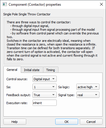
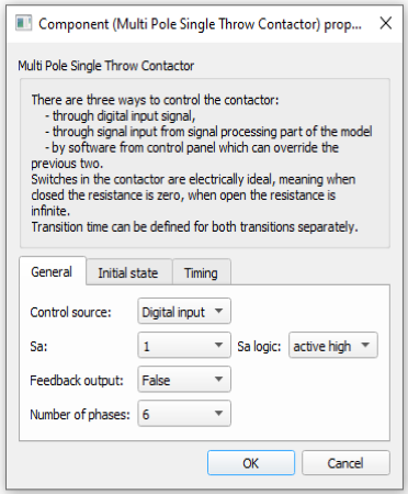
| General | Control source | Choose if the contactor is controlled by a digital input signal or through a signal from the model. |
| Sa | Contactor gate signal digital input channel address: Sa(1..N). | |
| Sa logic | Contactor gate logic (active_high or active_low) | |
| Feedback output | Enable contactor feedback Signal Processing output | |
| Signal type | Contactor feedback signal type | |
| Execution rate | Signal Processing execution rate | |
| Number of phases | For Multi Pole Single Throw (MPST) contactor, it is possible to choose a number of phases from 1 up to 10 | |
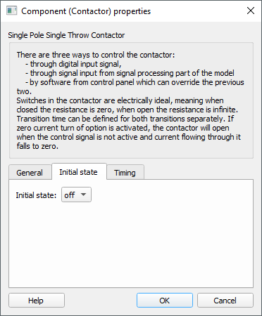
| Initial state | Initial state | Contactor initial state |
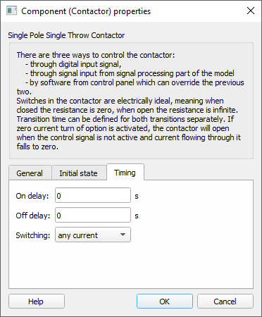
| Timing | On delay | Turn ON (closing) delay. |
| Off delay | Turn OFF (opening) delay. | |
| Switching | Choose between any current or zero current switching mode. |
Internal digital probes to the contactors
| Digital output variable name | Description |
|---|---|
| name_fb | Digital feedback signal signalizes the contactor state |
Contactor feedback Signal Processing output
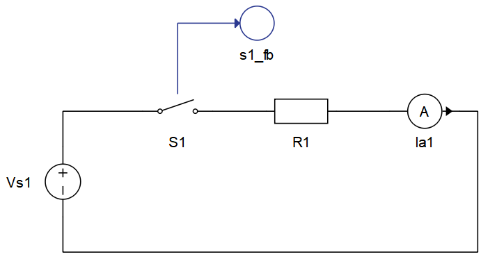
Signal Processing output for the contactor feedback signal can be enabled by setting the property Feedback output to True. This will create an output terminal on the contactor that can be used in the Signal Processing part of the schematic. This is illustrated in Figure 1.
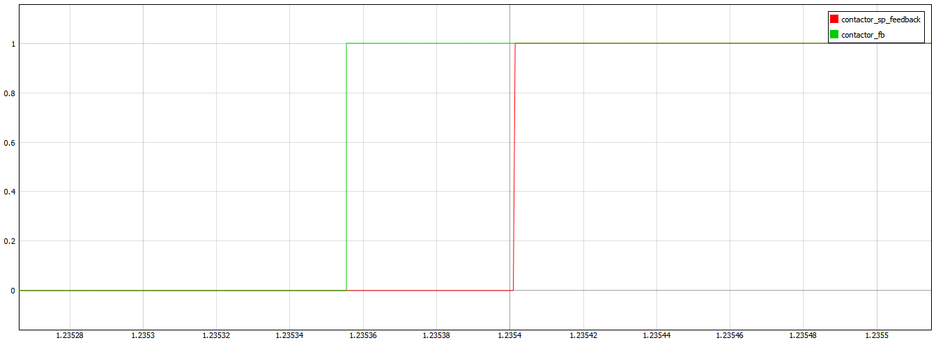
It is important to mention that the Signal Processing feedback output is delayed in comparison with the Digital feedback output signal due to the Signal Processing execution rate. Figure 2 illustrates this.
Digital Alias
If the contactor is controlled by digital input, the alias for digital input used by contactor will be created. The digital input alias will be available under the Digital inputs list alongside the existing Digital input signals. The alias will be shown as Contactor_name.Switch_name, where Contactor_name is the name of the contactor component and Switch_name is the name of the controllable switch in the contactor.