Grid
Description of the Grid component, which models a grid power source.
Component Icon
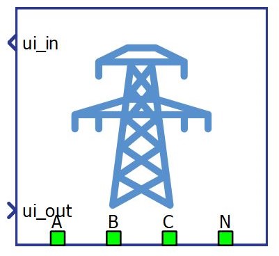
The Grid component models a grid power source and can be found in the Sources library category.
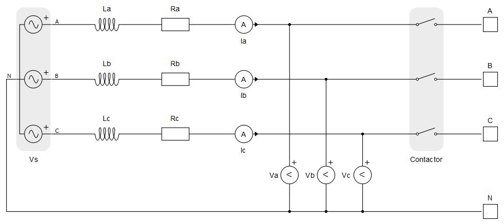
Grid power stage
The grid power stage consists of a three-phase voltage source, grid inductance with series resistance, and a contactor.
Grid component inputs and outputs
This component has one user interface input and one user interface output. User interface input and user interface output are arrays of 20 elements. Table 1 describes the input signals and their order. Table 2 describes the output signals and their order. All these signals are also defined in the corresponding Grid UI using Probes (for output signals) and Scada inputs (for input signals), as shown in Table 3. Grid UI is located in the same place in the library with the Grid component and it can be unlinked from the library and adopted to your specific needs. The unit [pu] is associated to nominal values, which are inserted as Grid component parameters or derived from them.
| Number | Input | Description | Input range |
|---|---|---|---|
| 0 | Connect | A digital input that closes the grid contactor. Contactor is closed when input value is high. | 0 or 1 |
| 1 | Grid_Vrms_cmd | Grid line voltage RMS command. [pu]. | > 0 |
| 2 | Grid_freq_cmd | Grid frequency command. [pu] | > 0 |
| 3-19 | reserved_ins | Inputs that are not used. |
| Number | Output | Description |
|---|---|---|
| 0 | Connect_fb | Digital signal active when grid contactor is closed. |
| 1 | Vrms_meas_kV | An analog output with the RMS value of measured grid voltage. [kV] |
| 2 | Fmeas_Hz | An analog output with the value of the measured grid voltage frequency. [Hz]. *Note: Limited by the internal PLL to the range [0.5, 1.5] pu |
| 3 | Pmeas_kW | An analog output with the instantaneous value of active power output of the grid. [kW] |
| 4 | Qmeas_kVAr | An analog output with the instantaneous value of reactive power output of the grid. [kVAr] |
| 5 | Smeas_kVA | An analog output with the instantaneous value of apparent power output of the grid. [kVA] |
| 6 | PFmeas | An analog output with value of the grid power factor. |
| 7-19 | reserved_outs | Outputs that are not used. |
| Grid UI | Grid UI internals |
|---|---|
|
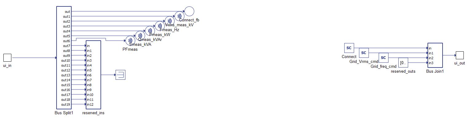
|
Grid component mask and parameters
Grid component mask consists of one tab for specifying parameters of the component.
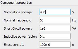
| Parameter | Code name | Description |
|---|---|---|
| Nominal line voltage | Vb | Grid nominal line voltage. [V] |
| Nominal frequency | f | Grid nominal frequency. [Hz] |
| Short Circuit power | Sb | Grid short circuit power. It determines the grid impedance value. [VA] |
| Inductive power factor | pf | Grid power factor when grid is short-circuited. It determines the resistance to reactance ratio. |
| Execution rate | Tfast | Execution rate of the internal signal processing. [s] |
Example
Overall behavior and control methodologies can be better understood with the use of the given example:
Model name: pv_plant_gen.tse
SCADA interface: SCADA_Panel.cus
Path: /examples/models/microgrid/pv_plant/pv_plant (generic)