Core marker
Description of the Core Marker component in Schematic Editor

In real-time/VHIL simulation, core markers are used to specify which separated circuit parts from the whole schematic diagram should be emulated on the same processor core. This component has only one parameter: Marker ID. Independent, not connected (or divided by coupling component) circuits from the full schematic model that have a core marker with the same Marker ID. are emulated on the same FPGA solver core.

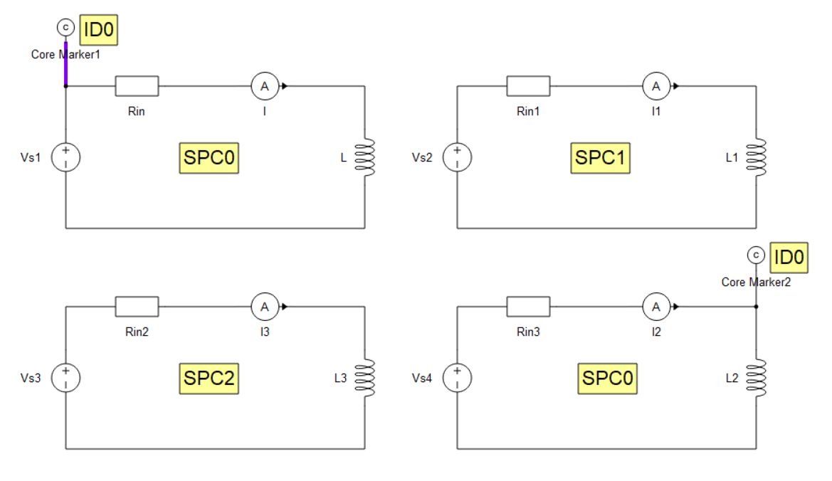
An example of a core marker use case in real-time/VHIL simulation is shown in Figure 2. There are four independent circuits shown. Without core marker components, this circuit would be emulated on 4 separate processor cores. In this case, with core markers, it would be emulated on 3 processing cores. Circuits marked with "1" and "4" have a core marker with the same IDs attached to themselves. That means that they would be emulated in same processing core (SPC). Circuits "2" and "3" would be emulated in separate cores, since they are not marked.

Another core marker use case for real-time/VHIL simulation is shown in Figure 3. This circuit, without core markers would be compiled into three SPCs. In the first one would be the grid and rectifier part, in the second SPC an inverter and the stator part of the doubly fed induction machine would be emulated (DF stator and rotor are internally separated), while in the third SPC the rotor part of the machine would be emulated. By using core markers with the same Marker ID on the grid and machines rotor side, these two parts are emulated on the same SPC. Simulation results are the same in both cases, but using these core markers, you can optimize the circuit arrangement into SPCs, so larger circuits can fit into the same device.

Properties
- Marker ID
- Marker's identification label. Circuits in the schematic model that have a core marker with the same MarkerID are emulated on the same FPGA solver core.