ANSI protective functions
Description of the suite of ANSI protective function components available in Schematic Editor.
ANSI protective function components overview
The ANSI protective functions are functions present in protective devices such as a relay. They are identified by the ANSI standard device numbers (ANSI / IEEE Standard C37.2 Standard for Electrical Power System Device Function Numbers, Acronyms, and Contact Designations). The objective of these functions is to protect electrical systems and components from damage when an unwanted event occurs.
- 27 Undervoltage
- 32 Directional Power
- 32L Low Forward Power
- 50 Instantaneous Overcurrent
- 50N Neutral Instantaneous Overcurrent
- 51 AC Inverse Time Overcurrent
- 51N Neutral AC Inverse Time Overcurrent
- 59 Overvoltage
- 59N Neutral Overvoltage
- 81O Over Frequency
- 81RF Fast Rate-of-Change of Frequency
- 81U Under Frequency
- External Trip
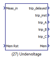
27 Undervoltage
The 27 Undervoltage device provides protection against voltage sags or detection of abnormally low network voltage to trigger automatic load shedding or source transfer.
| component | component dialog window | component parameters |
|---|---|---|
 |
 |
|
Inputs and outputs
The 27 Undervoltage protection function needs 2 default and 1 optional inputs to operate.
| Input | Description |
|---|---|
| Meas_in | An input coming from the meter component. This input is a list of length 30. The measurements used for this function are the voltages VAn_RMS, VBn_RMS and VCn_RMS (positions 10, 11 and 12 of the input list). |
| Mem Rst | A digital input that resets the trip memory. |
| Block | A digital input that blocks the protective function operation. This input is only available when the option Enable block function input is selected. |
The 27 Undervoltage protection function has 6 outputs.
| Output | Description |
|---|---|
| trip_delayed | A digital output with a delayed trip command. The time delay is defined in the component's mask. The output is high when the voltage in any of the three phases is under the voltage threshold and the time delay has passed. |
| trip_inst | A digital output with a instantaneous trip command. The output is high when the voltage in any of the three phases is under the voltage threshold. |
| trip_A | A digital output with a instantaneous trip command from an undervoltage fault on phase A. Output is high when trip command ocurred. |
| trip_B | A digital output with a instantaneous trip command from an undervoltage fault on phase B. Output is high when trip command ocurred. |
| trip_C | A digital output with a instantaneous trip command from an undervoltage fault on phase C. Output is high when trip command ocurred. |
| Mem | A digital output with the feedback of the trip memory. This output is high when the tripping occurs while the Mem Rst input is low. |
Parameters
The 27 Undervoltage protection function has 4 general parameters and 4 advanced options.
| Parameter | Code Name | Description |
|---|---|---|
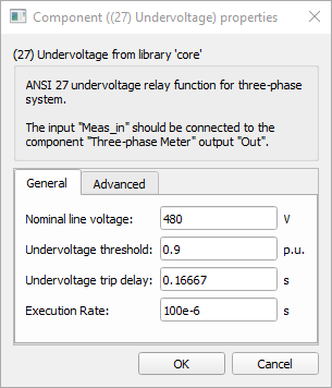
| Nominal line voltage | Vn | Nominal line-to-line voltage. [V] |
| Undervoltage threshold | UV_thresh | Percentage of the nominal voltage defined as the threshold to trip. [p.u.] |
| Undervoltage trip delay | UV_delay | Delay time to trip after fault occurrence. [s] |
| Execution rate | execution_rate | Execution rate of the component. [s] |
| Enable block function input | block_fcn | Checkbox that enables a digital input to block the protective function operation. Defaults to unchecked. |
| Enable instantaneous trip output | inst_trip | Checkbox that enables the three phase instantaneous trip digital output. Defaults to checked. |
| Enable individual phase trip output | phase_trip | Checkbox that enables the individual phase trip digital outputs. Defaults to checked. |
| Enable trip memory | mem_trip | Checkbox that enables the trip memory digital output. Defaults to checked. |
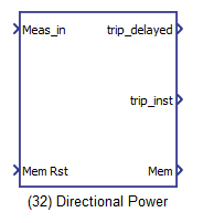
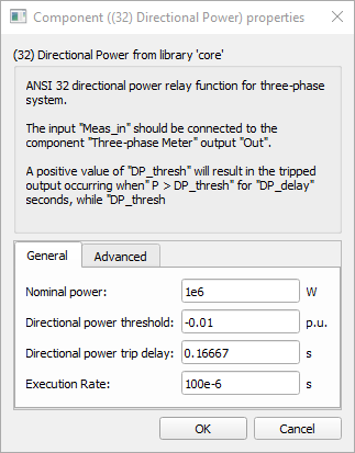
32 Directional Power
The Directional Power device provides protection to limit the flux of power flowing in a determinate direction.
| component | component dialog window | component parameters |
|---|---|---|
 |
 |
|
Inputs and outputs
The 32 Directional Power protection function needs 2 default and 1 optional inputs to operate.
| Input | Description |
|---|---|
| Meas_in | An input coming from the meter component. This input is a list of length 30. The measurement used for this function is the active power POWER_P (position 22 of the input list). |
| Mem Rst | A digital input that resets the trip memory. |
| Block | A digital input that blocks the protective function operation. This input is only available when the option Enable block function input is selected. |
The 32 Directional Power protection function has 3 outputs.
| Output | Description |
|---|---|
| trip_delayed | A digital output with a delayed trip command. The time delay is defined in the component's mask. The output is high when the active power flux is crosses the defined threshold and the time delay has passed. |
| trip_inst | A digital output with a instantaneous trip command. The output is high when the active power flux crosses the defined threshold. |
| Mem | A digital output with the feedback of the trip memory. This output is high when the tripping occurs while the Mem Rst input is low. |
Parameters
The 32 Directional Power protection function has 4 general parameters and 3 advanced options.
| Parameter | Code Name | Description |
|---|---|---|
| Nominal power | Pn | Nominal active power. [W] |
| Directional power threshold | DP_thresh | Percentage of the nominal power defined as the threshold to trip. If the threshold is positive, the trip occurrs for an active power greater than the threshold. If the threshold is negative, the trip occurrs if the power is smaller than the threshold (reverse power). [p.u.] |
| Directional Power trip delay | DP_delay | Delay time to trip after fault occurrence. [s] |
| Execution rate | execution_rate | Execution rate of the component. [s] |
| Enable block function input | block_fcn | Checkbox that enables a digital input to block the protective function operation. Defaults to unchecked. |
| Enable instantaneous trip output | inst_trip | Checkbox that enables the instantaneous trip digital output. Defaults to checked. |
| Enable trip memory | mem_trip | Checkbox that enables the trip memory digital output. Defaults to checked. |
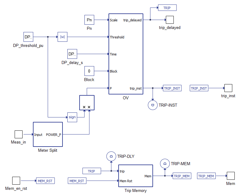
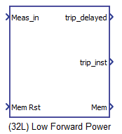
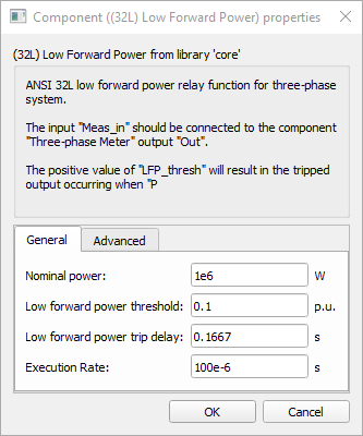
32L Low Forward Power
The Low Forward Power device provides detection of a power flow below the defined threshold. Can be used to invalidate an operator's open breaker command when a generator is providing high power to the network.
| component | component dialog window | component parameters |
|---|---|---|
 |
 |
|
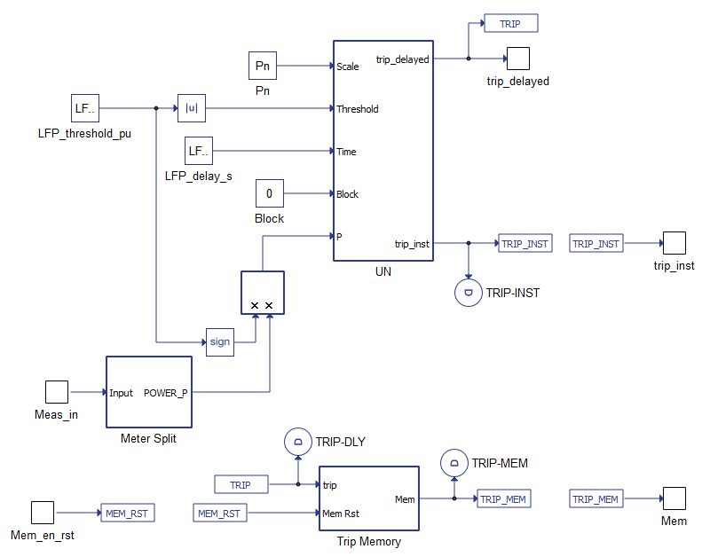
Inputs and outputs
The 32L Low Forward Power protection function needs 2 default and 1 optional inputs to operate.
| Input | Description |
|---|---|
| Meas_in | An input coming from the meter component. This input is a list of length 30. The measurement used for this function is the active power POWER_P (position 22 of the input list). |
| Mem Rst | A digital input that resets the trip memory. |
| Block | A digital input that blocks the protective function operation. This input is only available when the option Enable block function input is selected. |
The 32L Low Forward Power protection function has 3 outputs.
| Output | Description |
|---|---|
| trip_delayed | A digital output with a delayed trip command. The time delay is defined in the component's mask. The output is high when the active power flux is crosses the defined threshold and the time delay has passed. |
| trip_inst | A digital output with a instantaneous trip command. The output is high when the active power flux crosses the defined threshold. |
| Mem | A digital output with the feedback of the trip memory. This output is high when the tripping occurs while the Mem Rst input is low. |
Parameters
The 32L Low Forward Power protection function has 4 general parameters and 3 advanced options.
| Parameter | Code Name | Description |
|---|---|---|
| Nominal power | Pn | Nominal active power. [W] |
| Low forward power threshold | LFP_thresh | Percentage of the nominal power defined as the threshold to trip. If the threshold is positive, the trip occurs for an active power smaller than the threshold. If the threshold is negative, the trip occurs if the power is greater than the threshold (reverse power). [p.u.] |
| Directional Power trip delay | LFP_delay | Delay time to trip after fault occurrence. [s] |
| Execution rate | execution_rate | Execution rate of the component. [s] |
| Enable block function input | block_fcn | Checkbox that enables a digital input to block the protective function operation. Defaults to unchecked. |
| Enable instantaneous trip output | inst_trip | Checkbox that enables the instantaneous trip digital output. Defaults to checked. |
| Enable trip memory | mem_trip | Checkbox that enables the trip memory digital output. Defaults to checked. |
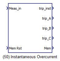
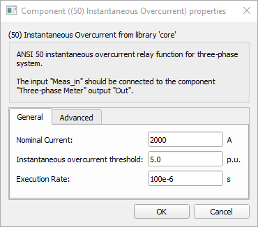
50 Instantaneous Overcurrent
The 50 Instantaneous Overcurrent device provides instantaneous protection against high currents.
| component | component dialog window | component parameters |
|---|---|---|
 |
 |
|
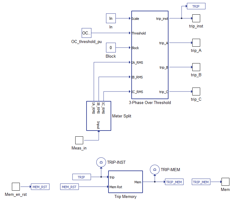
Inputs and outputs
The 50 Instantaneous Overcurrent protection function needs 2 default and 1 optional inputs to operate.
| Input | Description |
|---|---|
| Meas_in | An input coming from the meter component. This input is a list of length 30. The measurements used for this function are the currents IA_RMS, IB_RMS and IC_RMS (positions 18, 19 and 20 of the input list). |
| Mem Rst | A digital input that resets the trip memory. |
| Block | A digital input that blocks the protective function operation. This input is only available when the option Enable block function input is selected. |
The 50 Instantaneous Overcurrent protection function has 5 outputs.
| Output | Description |
|---|---|
| trip_inst | A digital output with a instantaneous trip command. The output is high when any of the currents crosses the defined threshold. |
| trip_A | A digital output with a instantaneous trip command. The output is high when the current on phase A crosses the defined threshold. |
| trip_B | A digital output with a instantaneous trip command. The output is high when the current on phase B crosses the defined threshold. |
| trip_C | A digital output with a instantaneous trip command. The output is high when the current on phase C crosses the defined threshold. |
| Mem | A digital output with the feedback of the trip memory. This output is high when the tripping occurs while the Mem Rst input is low. |
Parameters
The 50 Instantaneous Overcurrent protection function has 3 general parameters and 3 advanced options.
| Parameter | Code Name | Description |
|---|---|---|
| Nominal current | In | Nominal current in RMS. [A] |
| Instantaneous overcurrent threshold | OC_thresh | Percentage of the nominal current defined as the threshold to trip. [p.u.] |
| Execution rate | execution_rate | Execution rate of the component. [s] |
| Enable block function input | block_fcn | Checkbox that enables a digital input to block the protective function operation. Defaults to unchecked. |
| Enable individual phase trip output | phase_trip | Checkbox that enables the individual phase trip digital outputs. Defaults to checked. |
| Enable trip memory | mem_trip | Checkbox that enables the trip memory digital output. Defaults to checked. |
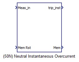
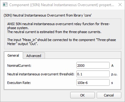
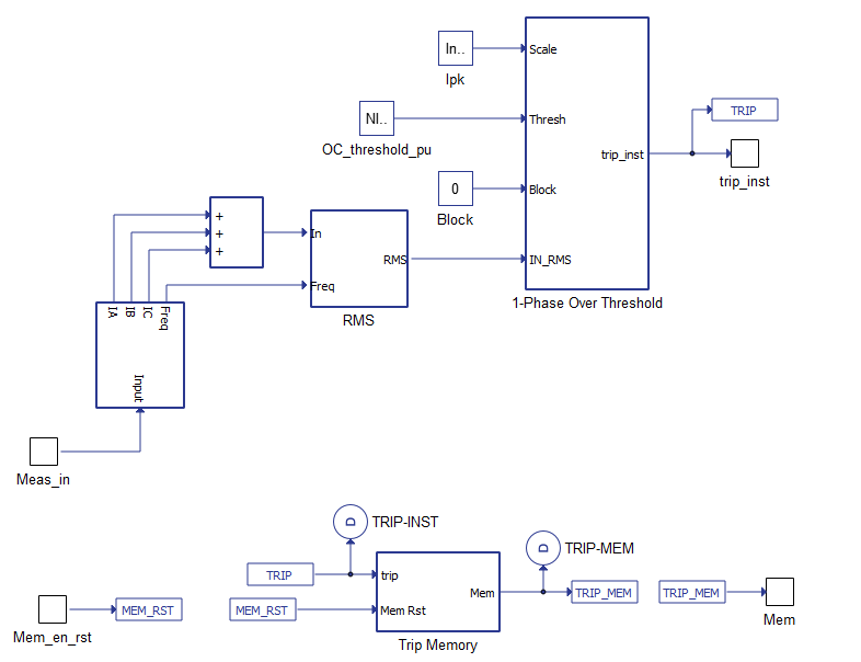
50N Neutral Instantaneous Overcurrent
The 50N Neutral Instantaneous Overcurrent device provides instantaneous protection against high neutral currents.
| component | component dialog window | component parameters |
|---|---|---|
 |
 |
|
Inputs and outputs
The 50N Neutral Instantaneous Overcurrent protection function needs 2 default and 1 optional inputs to operate.
| Input | Description |
|---|---|
| Meas_in | An input coming from the meter component. This input is a list of length 30. The measurements used for this function are the currents IA, IB and IC (positions 6, 7 and 8 of the input list). |
| Mem Rst | A digital input that resets the trip memory. |
| Block | A digital input that blocks the protective function operation. This input is only available when the option Enable block function input is selected. |
The 50N Neutral Instantaneous Overcurrent protection function has 2 outputs.
| Output | Description |
|---|---|
| trip_inst | A digital output with a instantaneous trip command. The output is high when any of the currents crosses the defined threshold. |
| Mem | A digital output with the feedback of the trip memory. This output is high when the tripping occurs while the Mem Rst input is low. |
Parameters
The 50N Neutral Instantaneous Overcurrent protection function has 3 general parameters and 2 advanced options.
| Parameter | Code Name | Description |
|---|---|---|
| Nominal current | In | Nominal current in RMS. [A] |
| Neutral instantaneous overcurrent threshold | OC_thresh | Percentage of the nominal current defined as the threshold to trip. [p.u.] |
| Execution rate | execution_rate | Execution rate of the component. [s] |
| Enable block function input | block_fcn | Checkbox that enables a digital input to block the protective function operation. Defaults to unchecked. |
| Enable trip memory | mem_trip | Checkbox that enables the trip memory digital output. Defaults to checked. |
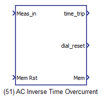
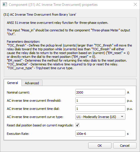
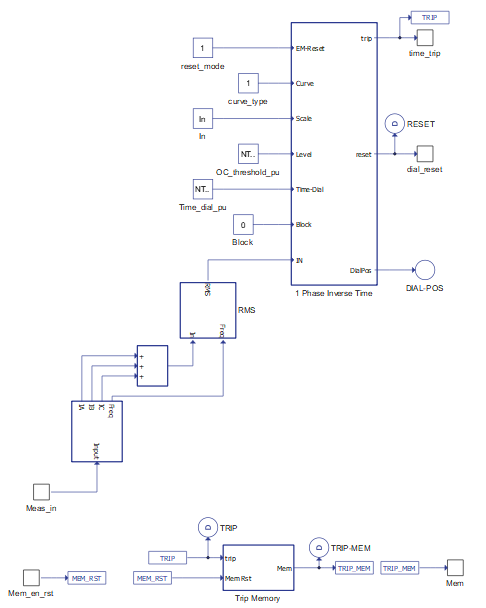
51 AC Inverse Time Overcurrent
The 51 AC Inverse Time Overcurrent device provides protection against high currents based on a time vs. current curve.
| component | component dialog window | component parameters |
|---|---|---|
 |
 |
|
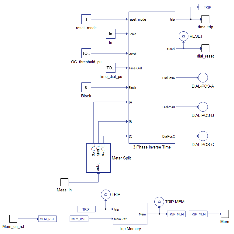
Inputs and outputs
The 51 AC Inverse Time Overcurrent protection function needs 2 default and 1 optional inputs to operate.
| Input | Description |
|---|---|
| Meas_in | An input coming from the meter component. This input is a list of length 30. The measurements used for this function are the currents IA_RMS, IB_RMS and IC_RMS (positions 18, 19 and 20 of the input list). |
| Mem Rst | A digital input that resets the trip memory. |
| Block | A digital input that blocks the protective function operation. This input is only available when the option Enable block function input is selected. |
The 51 AC Inverse Time Overcurrent protection function has 3 outputs.
| Output | Description |
|---|---|
| time_trip | A digital output with a instantaneous trip command. The output is high when any of the currents dials wind-up to trip position. |
| dial_reset | A digital output with a feedback on the dial states. The output is high when all dials are at start position. |
| Mem | A digital output with the feedback of the trip memory. This output is high when the tripping occurs while the Mem Rst input is low. |
Parameters
The 51 AC Inverse Time Overcurrent protection function has 6 general parameters and 2 advanced options.
| Parameter | Code Name | Description |
|---|---|---|
| Nominal current | In | Nominal current in RMS. [A] |
| AC inverse time overcurrent threshold | TOC_thresh | Percentage of the nominal current defined as the threshold to enter in trip curve zone. [p.u.] |
| AC inverse time overcurrent time dial | TOC_timeDial | Constant that adjust the time to trip by offsetting the trip curve. |
| AC inverse time overcurrent curve type | TOC_curve_type | Combo box to choose which trip curve to use. Options available are:
|
| Reset dial position based on current magnitude | EM_reset | Checkbox to define how the dial position are reset. If checked, the current is taken into account, otherwise, the dial position is reset to zero once the current is below the threshold. |
| Execution rate | Execution rate of the component. [s] | Execution rate of the component. [s] |
| Enable block function input | block_fcn | Checkbox that enables a digital input to block the protective function operation. Defaults to unchecked. |
| Enable trip memory | mem_trip | Checkbox that enables the trip memory digital output. Defaults to checked. |
When the AC inverse time overcurrent curve type is set to Custom Curve a new tab named Curve Definition appears. The properties on this tab are used in the trip and reset curves.
Trip curve:
Reset curve:
| Parameter | Code Name | Description |
|---|---|---|
| Trip curve parameter A | curve_prm_A | Ratio of the disk damping factor and the restraining spring torque constant |
| Trip curve parameter B | curve_prm_B | Disk inertia constant |
| Trip curve parameter P | curve_prm_P | Trip curve exponent constant |
| Reset curve parameter C | curve_prm_C | Reset curve proportional constant |
| Reset curve parameter Pr | curve_prm_Pr | Reset curve exponent constant |
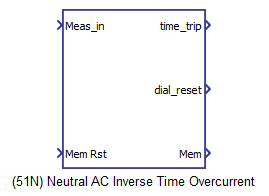
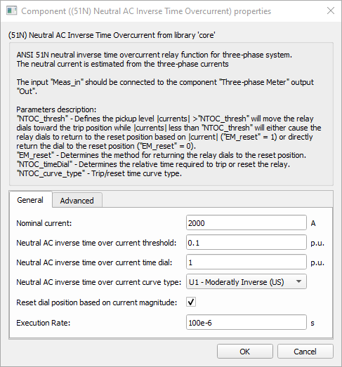
51N Neutral AC Inverse Time Overcurrent
The 51N Neutral AC Inverse Time Overcurrent device provides protection against high currents based on a time vs. current curve.
| component | component dialog window | component parameters |
|---|---|---|
 |
 |
|
Inputs and outputs
The 51N Neutral AC Inverse Time Overcurrent protection function needs 2 default and 1 optional inputs to operate.
| Input | Description |
|---|---|
| Meas_in | An input coming from the meter component. This input is a list of length 30. The measurements used for this function are the currents IA, IB and IC (positions 6, 7 and 8 of the input list). |
| Mem Rst | A digital input that resets the trip memory. |
| Block | A digital input that blocks the protective function operation. This input is only available when the option Enable block function input is selected. |
The 51N Neutral AC Inverse Time Overcurrent protection function has 3 outputs.
| Output | Description |
|---|---|
| time_trip | A digital output with a instantaneous trip command. The output is high when any of the currents dials wind-up to trip position. |
| dial_reset | A digital output with a feedback on the dial states. The output is high when all dials are at start position. |
| Mem | A digital output with the feedback of the trip memory. This output is high when the tripping occurs while the Mem Rst input is low. |
Parameters
The 51N Neutral AC Inverse Time Overcurrent protection function has 6 general parameters and 2 advanced options.
| Parameter | Code Name | Description |
|---|---|---|
| Nominal current | In | Nominal current in RMS. [A] |
| Neutral AC inverse time overcurrent threshold | TOC_thresh | Percentage of the nominal current defined as the threshold to enter in trip curve zone. [p.u.] |
| Neutral AC inverse time overcurrent time dial | TOC_timeDial | Constant that adjust the time to trip by offsetting the trip curve. |
| Neutral AC inverse time overcurrent curve type | TOC_curve_type | Combo box to choose which trip curve to use. Options available are:
|
| Reset dial position based on current magnitude | EM_reset | Checkbox to define how the dial position are reset. If checked, the current is taken into account, otherwise, the dial position is reset to zero once the current is below the threshold. |
| Execution rate | Execution rate of the component. [s] | Execution rate of the component. [s] |
| Enable block function input | block_fcn | Checkbox that enables a digital input to block the protective function operation. Defaults to unchecked. |
| Enable trip memory | mem_trip | Checkbox that enables the trip memory digital output. Defaults to checked. |
When the AC inverse time overcurrent curve type is set to Custom Curve a new tab named Curve Definition appears. The properties on this tab are used in the trip and reset curves.
Trip curve:
Reset curve:
| Parameter | Code Name | Description |
|---|---|---|
| Trip curve parameter A | curve_prm_A | Ratio of the disk damping factor and the restraining spring torque constant |
| Trip curve parameter B | curve_prm_B | Disk inertia constant |
| Trip curve parameter P | curve_prm_P | Trip curve exponent constant |
| Reset curve parameter C | curve_prm_C | Reset curve proportional constant |
| Reset curve parameter Pr | curve_prm_Pr | Reset curve exponent constant |
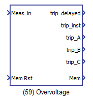
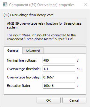
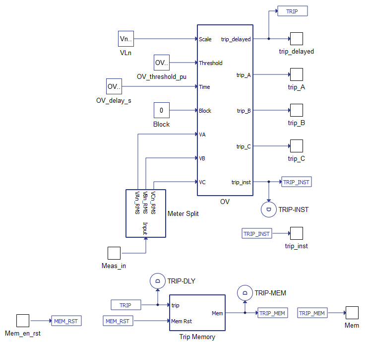
59 Overvoltage
The 59 Overvoltage device provides protection against voltage swells.
| component | component dialog window | component parameters |
|---|---|---|
 |
 |
|
Inputs and outputs
The 59 Overvoltage protection function needs 2 default and 1 optional inputs to operate.
| Input | Description |
|---|---|
| Meas_in | An input coming from the meter component. This input is a list of length 30. The measurements used for this function are the voltages VAn_RMS, VBn_RMS and VCn_RMS (positions 10, 11 and 12 of the input list). |
| Mem Rst | A digital input that resets the trip memory. |
| Block | A digital input that blocks the protective function operation. This input is only available when the option Enable block function input is selected. |
The 59 Overvoltage protection function has 6 outputs.
| Output | Description |
|---|---|
| trip_delayed | A digital output with a delayed trip command. The time delay is defined in the component's mask. The output is high when the voltage in any of the three phases is over the voltage threshold and the time delay has passed. |
| trip_inst | A digital output with a instantaneous trip command. The output is high when the voltage in any of the three phases is over the voltage threshold. |
| trip_A | A digital output with a instantaneous trip command from an overvoltage fault on phase A. Output is high when trip command occurred. |
| trip_B | A digital output with a instantaneous trip command from an overvoltage fault on phase B. Output is high when trip command occurred. |
| trip_C | A digital output with a instantaneous trip command from an overvoltage fault on phase C. Output is high when trip command occurred. |
| Mem | A digital output with the feedback of the trip memory. This output is high when the tripping occurs while the Mem Rst input is low. |
Parameters
The 59 Overvoltage protection function has 4 general parameters and 4 advanced options.
| Parameter | Code Name | Description |
|---|---|---|
| Nominal line voltage | Vn | Nominal line-to-line voltage. [V] |
| Overvoltage threshold | OV_thresh | Percentage of the nominal voltage defined as the threshold to trip. [p.u.] |
| Overvoltage trip delay | OV_delay | Delay time to trip after fault occurrence. [s] |
| Execution rate | execution_rate | Execution rate of the component. [s] |
| Enable block function input | block_fcn | Checkbox that enables a digital input to block the protective function operation. Defaults to unchecked. |
| Enable instantaneous trip output | inst_trip | Checkbox that enables the three phase instantaneous trip digital output. Defaults to checked. |
| Enable individual phase trip output | phase_trip | Checkbox that enables the individual phase trip digital outputs. Defaults to checked. |
| Enable trip memory | mem_trip | Checkbox that enables the trip memory digital output. Defaults to checked. |
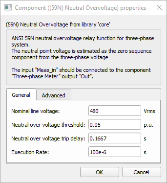
59N Neutral Overvoltage
The 59N Neutral Overvoltage device provides protection against voltage swells.
| component | component dialog window | component parameters |
|---|---|---|
 |
 |
|
Inputs and outputs
The 59N Neutral Overvoltage protection function needs 2 default and 1 optional inputs to operate.
| Input | Description |
|---|---|
| Meas_in | An input coming from the meter component. This input is a list of length 30. The measurements used for this function are the voltages VAn, VBn and VCn (positions 0, 1 and 2 of the input list). |
| Mem Rst | A digital input that resets the trip memory. |
| Block | A digital input that blocks the protective function operation. This input is only available when the option Enable block function input is selected. |
The 59N Neutral Overvoltage protection function has 3 outputs.
| Output | Description |
|---|---|
| trip_delayed | A digital output with a delayed trip command. The time delay is defined in the component's mask. The output is high when the voltage in any of the three phases is over the voltage threshold and the time delay has passed. |
| trip_inst | A digital output with a instantaneous trip command. The output is high when the voltage in any of the three phases is over the voltage threshold. |
| Mem | A digital output with the feedback of the trip memory. This output is high when the tripping occurs while the Mem Rst input is low. |
Parameters
The 59N Neutral Overvoltage protection function has 4 general parameters and 3 advanced options.
| Parameter | Code Name | Description |
|---|---|---|
| Nominal line voltage | Vn | Nominal line-to-line voltage. [V] |
| Neutral overvoltage threshold | OV_thresh | Percentage of the nominal voltage defined as the threshold to trip. [p.u.] |
| Neutral overvoltage trip delay | OV_delay | Delay time to trip after fault occurrence. [s] |
| Execution rate | execution_rate | Execution rate of the component. [s] |
| Enable block function input | block_fcn | Checkbox that enables a digital input to block the protective function operation. Defaults to unchecked. |
| Enable instantaneous trip output | inst_trip | Checkbox that enables the three phase instantaneous trip digital output. Defaults to checked. |
| Enable trip memory | mem_trip | Checkbox that enables the trip memory digital output. Defaults to checked. |
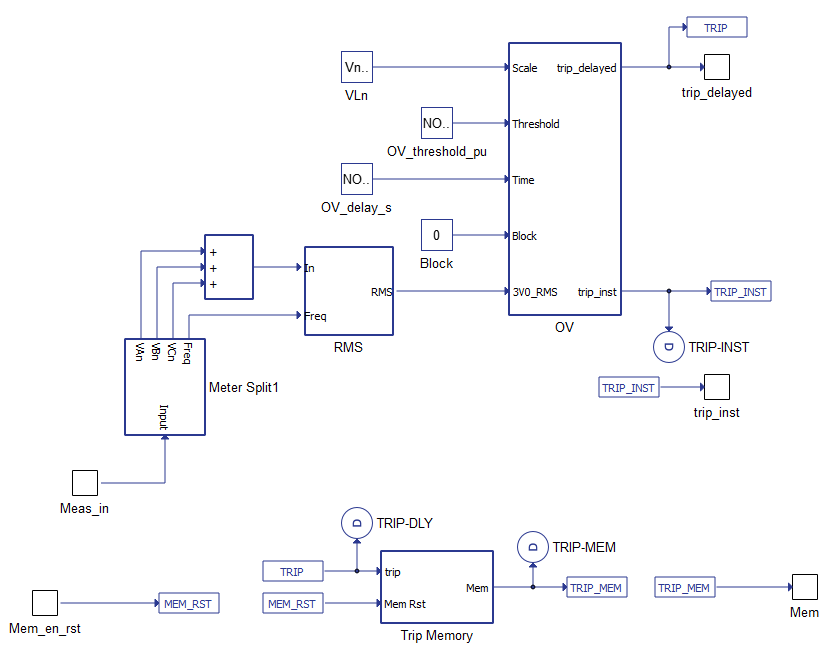
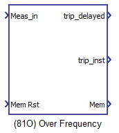
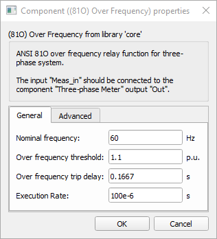
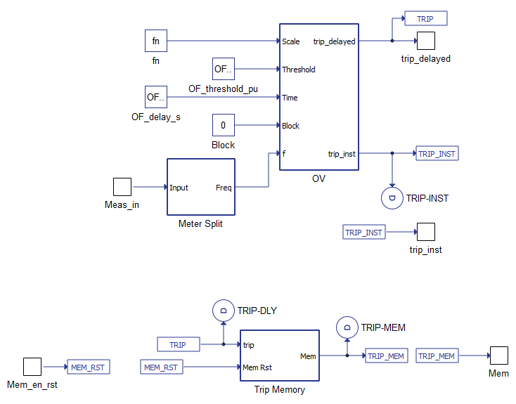
81O Over Frequency
The 81O Over Frequency device provides protection against frequency swells.
| component | component dialog window | component parameters |
|---|---|---|
 |
 |
|
Inputs and outputs
The 81O Over frequency protection function needs 2 default and 1 optional inputs to operate.
| Input | Description |
|---|---|
| Meas_in | An input coming from the meter component. This input is a list of length 30. The measurements used for this function is the frequency Freq (position 9 of the input list). |
| Mem Rst | A digital input that resets the trip memory. |
| Block | A digital input that blocks the protective function operation. This input is only available when the option Enable block function input is selected. |
The 81O Over frequency protection function has 3 outputs.
| Output | Description |
|---|---|
| trip_delayed | A digital output with a delayed trip command. The time delay is defined in the component's mask. The output is high when the frequency is over the threshold and the time delay has passed. |
| trip_inst | A digital output with a instantaneous trip command. The output is high when the frequency is over the threshold. |
| Mem | A digital output with the feedback of the trip memory. This output is high when the tripping occurs while the Mem Rst input is low. |
Parameters
The 81O Over Frequency protection function has 4 general parameters and 3 advanced options.
| Parameter | Code Name | Description |
|---|---|---|
| Nominal frequency | fn | Nominal frequency. [Hz] |
| Over frequency threshold | OF_thresh | Percentage of the nominal frequency defined as the threshold to trip. [p.u.] |
| Over frequency trip delay | OF_delay | Delay time to trip after fault occurrence. [s] |
| Execution rate | execution_rate | Execution rate of the component. [s] |
| Enable block function input | block_fcn | Checkbox that enables a digital input to block the protective function operation. Defaults to unchecked. |
| Enable instantaneous trip output | inst_trip | Checkbox that enables the three phase instantaneous trip digital output. Defaults to checked. |
| Enable trip memory | mem_trip | Checkbox that enables the trip memory digital output. Defaults to checked. |
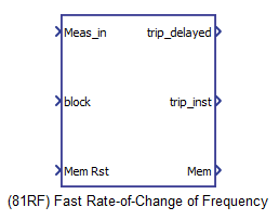
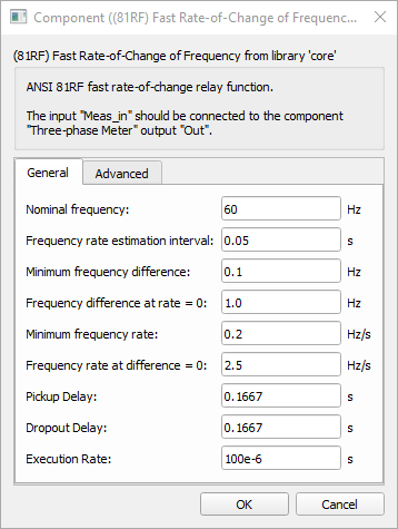
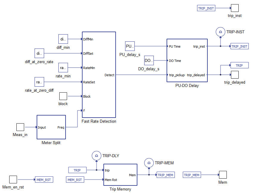
81RF Fast Rate-of-Change of Frequency
The 81RF Fast Rate-of-Change of Frequency device provides protection against fast changes in frequency.
| component | component dialog window | component parameters |
|---|---|---|
 |
 |
|
Inputs and outputs
The 81RF Fast Rate-of-Change of Frequency protection function needs 2 default inputs and 1 optional to operate.
| Input | Description |
|---|---|
| Meas_in | An input coming from the meter component. This input is a list of length 30. The measurements used for this function is the frequency Freq (position 9 of the input list). |
| Block | A digital input that blocks the protective function operation. This input is only available when the option Enable block function input is selected. |
| Mem Rst | A digital input that resets the trip memory. |
The 81RF Fast Rate-of-Change of Frequency protection function has 3 outputs.
| Output | Description |
|---|---|
| trip_delayed | A digital output with a delayed trip command. |
| trip_inst | A digital output with a instantaneous trip command. |
| Mem | A digital output with the feedback of the trip memory. This output is high when the tripping occurs while the Mem Rst input is low. |
Parameters
The 81RF Fast Rate-of-Change of Frequency protection function has 9 general parameters and 3 advanced options.
| Parameter | Code Name | Description |
|---|---|---|
| Nominal frequency | fn | Nominal frequency. [Hz] |
| Frequency rate estimation interval | rate_interval | Time interval for frequency rate estimation. [s] |
| Minimum frequency difference | diffMin | Delay time to trip after fault occurrence. [Hz] |
| Frequency difference at rate = 0 | diffSet | Frequency difference when the rate is equal to zero. [Hz] |
| Minimum frequency rate | rateMin | Minimum frequency rate. [Hz/s] |
| Frequency rate at difference = 0 | rateSet | Frequency rate when difference is equal to zero. [Hz/s] |
| Pickup Delay | PU_delay | Pickup delay. [s] |
| Dropout Delay | DO_delay | Dropout delay. [s] |
| Execution rate | execution_rate | Execution rate of the component. [s] |
| Enable block function input | block_fcn | Checkbox that enables a digital input to block the protective function operation. Defaults to checked. |
| Enable instantaneous trip output | inst_trip | Checkbox that enables the three phase instantaneous trip digital output. Defaults to checked. |
| Enable trip memory | mem_trip | Checkbox that enables the trip memory digital output. Defaults to checked. |
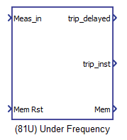
81U Under Frequency
The 81U Under Frequency device provides protection against frequency swells.
| component | component dialog window | component parameters |
|---|---|---|
 |
 |
|
Inputs and outputs
The 81U Under frequency protection function needs 2 default and 1 optional inputs to operate.
| Input | Description |
|---|---|
| Meas_in | An input coming from the meter component. This input is a list of length 30. The measurements used for this function is the frequency Freq (position 9 of the input list). |
| Mem Rst | A digital input that resets the trip memory. |
| Block | A digital input that blocks the protective function operation. This input is only available when the option Enable block function input is selected. |
The 81U Under frequency protection function has 3 outputs.
| Output | Description |
|---|---|
| trip_delayed | A digital output with a delayed trip command. The time delay is defined in the component's mask. The output is high when the frequency is under the threshold and the time delay has passed. |
| trip_inst | A digital output with a instantaneous trip command. The output is high when the frequency is under the threshold. |
| Mem | A digital output with the feedback of the trip memory. This output is high when the tripping occurs while the Mem Rst input is low. |
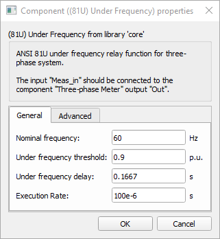
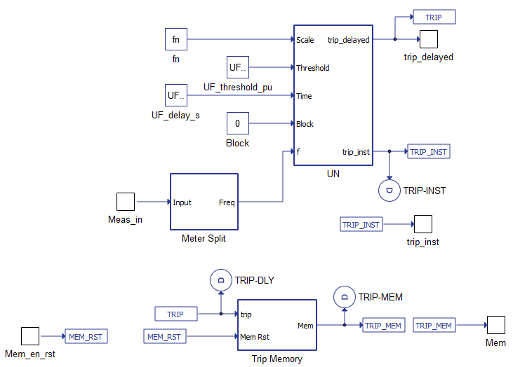
Parameters
The 81U Under Frequency protection function has 4 general parameters and 3 advanced options.
| Parameter | Code Name | Description |
|---|---|---|
| Nominal frequency | fn | Nominal frequency. [Hz] |
| Under frequency threshold | UF_thresh | Percentage of the nominal frequency defined as the threshold to trip. [p.u.] |
| Under frequency trip delay | UF_delay | Delay time to trip after fault occurrence. [s] |
| Execution rate | execution_rate | Execution rate of the component. [s] |
| Enable block function input | block_fcn | Checkbox that enables a digital input to block the protective function operation. Defaults to unchecked. |
| Enable instantaneous trip output | inst_trip | Checkbox that enables the three phase instantaneous trip digital output. Defaults to checked. |
| Enable trip memory | mem_trip | Checkbox that enables the trip memory digital output. Defaults to checked. |
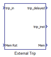
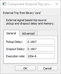
External Trip
The External Trip device provide a relay a feature to receive trip commands from an external protective function.
| component | component dialog window | component parameters |
|---|---|---|
 |
 |
|
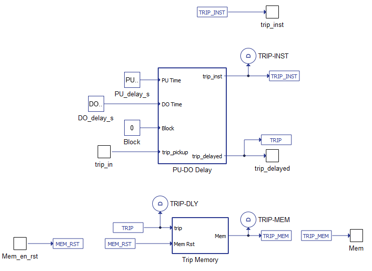
Inputs and outputs
The External Trip function needs 2 default and 1 optional inputs to operate.
| Input | Description |
|---|---|
| trip_in | A digital input with a trip command coming from an external protective function. |
| Mem Rst | A digital input that resets the trip memory. |
| Block | A digital input that blocks the protective function operation. This input is only available when the option Enable block function input is selected. |
The External Trip function has 3 outputs.
| Output | Description |
|---|---|
| trip_delayed | A digital output with a delayed trip command. The time delay is defined in the component's mask. |
| trip_inst | A digital output with a instantaneous trip command. |
| Mem | A digital output with the feedback of the trip memory. This output is high when the tripping occurs while the Mem Rst input is low. |
Parameters
The External Trip function has 3 default parameters and 3 advanced options.
| Parameter | Code Name | Description |
|---|---|---|
| Pickup Delay | PU_delay | Pickup delay [s] |
| Dropout Delay | DO_delay | Dropout Delay [s] |
| Execution rate | execution_rate | Execution rate of the component. [s] |
| Enable block function input | block_fcn | Checkbox that enables a digital input to block the protective function operation. Defaults to unchecked. |
| Enable instantaneous trip output | inst_trip | Checkbox that enables the three phase instantaneous trip digital output. Defaults to checked. |
| Enable trip memory | mem_trip | Checkbox that enables the trip memory digital output. Defaults to checked. |
Example
Overall behavior and control methodologies can be better understood with the use of the given ANSI protective functions example:
Model name: protective_functions.tse
SCADA interface: SCADA_Panel.cus
Path: /examples/models/microgrid/protective_ansi_functions/