Control for MMC Leg - NLC
Description of the Control for MMC Leg- NLC component in Schematic Editor which can be used for controlling the MMC Leg Switching Function.
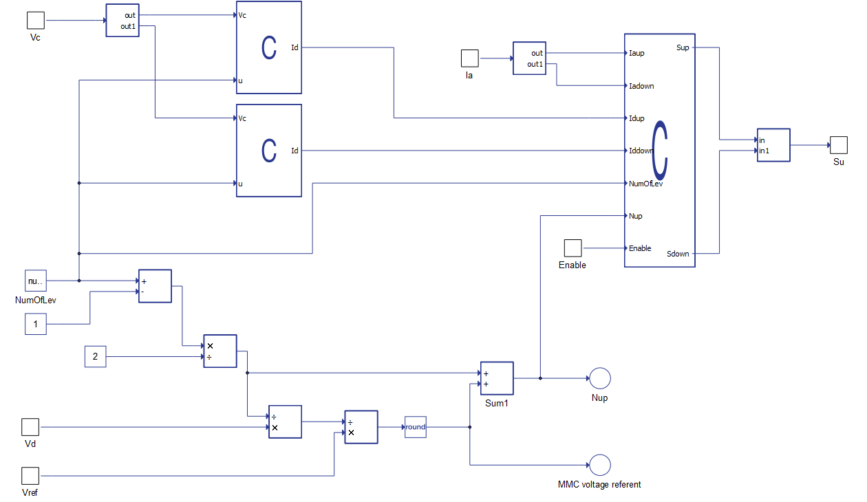
Control for MMC Leg - NLC overview
The Control for MMC Leg - NLC uses the nearest level control balancing method for generating a reference voltage level. The MMC Leg - Switching Function component is controlled by the feedback of the currents in the arms (Ia) as well as the voltage values on the capacitors (Vc). Additionally, a SCADA Input component should be added to the model and connected to the Enable port on the Control for MMC Leg - NLC component. It is necessary to set the SCADA Input component's Enable property to 1 and the inputs Vd and Vref on the Control for MMC Leg - NLC component to the desired values.
Ports
- Enable
- A digital input that comands the On/Off state of the Control for MMC Leg - NLC. It is ON when input is high.
- Vd
- An analog input that sets a nominal voltage of DC link.
- Vref
- An analog input that sets a reference sinusoidal voltage waveform.
- Vc
- An analog input that provides the measured voltages across the capacitors (in both arms of the MMC Leg - Switching Function) as an array.
- Ia
- An analog input that provides the measured currents (in both arms of the MMC Leg - Switching Function) as an array.
- Su
- A digital output that determinates which sub-modules in the MMC Leg - Switching Function component will be inserted in the circuit.
Properties
- Number of levels
- Number of MMC Leg - Switching Function voltage levels
- Dimensions of the input Vc and the output Su are: 2*(Number of levels - 1).
- Execution rate
- Execution rate of all signal processing components in a model.