Maximum number of communication lines between cores and devices
This section describes maximum amount of communication lines between Standard Processing Cores and HIL devices. It shows resource utilization by coupling components.
As explained in Model partitioning, to fit within the fixed time-step requirements models are divided into smaller segments and simulated on multiple cores of the same device, or even multiple devices. However, there is a constraint regarding the number of connections between cores and devices. Each core/device coupling component from Model Partitioning Components utilizes a specific number of communication lines for exchanging electrical variables.
Maximum number of lines between two Standard Processing Cores in the same device
The FPGA solver has several building blocks of the circuit solver - Standard Processing Cores (SPC). These blocks are interconnected through dedicated communication lines which allows them to exchange variables with a single simulation step delay, as shown in Figure 1.
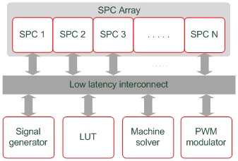
Maximum number of electrical variables that can be exhanged between any two cores is 4*.
Additional communication lines
In Figure 1 there is a separate entity called Look Up Tables (LUT). Every SPC is connected to the LUT. In cases when all 4 standard communication lines between two cores are fully utilized, LUT can be used as a resource for additional lines. Since LUT is a resource on a device level, the number of additional lines is a global resource (it does not refer to every two cores like standard lines) and its utilization increases with every core pair that uses it. Number of available additional lines is equal to the number of Look Up Tables in a device, divided by 2.
*Theoretically, the maximum number of electrical variables between two cores can be 4 plus the total number of additional lines through LUT. However, LUT utilization can be increased by other components and other core pairs.
Maximum number of lines between multiple devices
- Maximum number of electrical variables that one SPC can send to and receive from SPCs in other devices is 8
- Maximum number of electrical variables that one device can send to and receive from other devices is 16
More details about multi-HIL communication parameters can be found in Multi-HIL system architecture parameters.
Coupling components - number of lines
- Single Phase Core/Device Coupling - one variable
- Three Phase Core/Device Coupling - two variables
- Four Phase Core/Device Coupling - three variables
- Five Phase Core Coupling - four variables
- Single Phase TLM Core/Device Coupling - one variable
- Three Phase TLM Core/Device Coupling - three variables
- Four Phase TLM Core/Device Coupling - three variable
- Five Phase TLM Core Coupling - four variables