Multi-HIL specific circuit partitioning
This section describes dividing circuits in multi-HIL systems
In multi-HIL systems, complex circuits can be divided into smaller chunks which run on separate HIL devices. There are only a few rules that must be followed to correctly divide circuits into separate HIL devices. In this explanation, HIL markers will be color-coded to make the description more intuitive.
It is important to remember that there are two ways in which circuits can be divided: by using device markers and by using device coupling. In multi-HIL systems circuits must be divided by device markers. However, device markers can be combined with device couplings, which allows you to fully optimize the use of computing resources in a multi-HIL system.
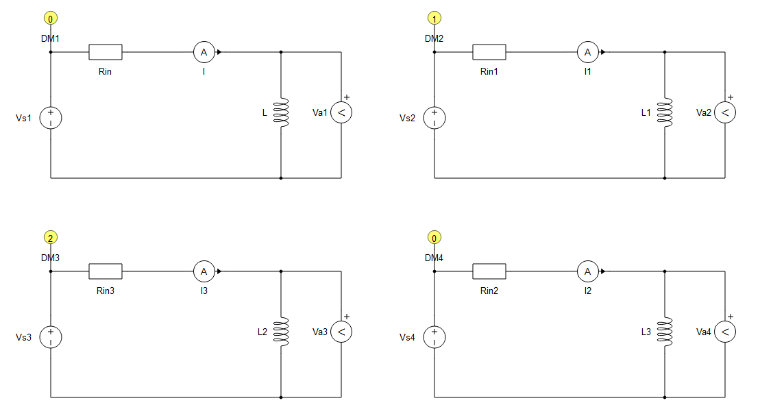
Firstly, circuits can be divided into different HIL devices without coupling components, only by using device markers. In this case, circuits must not be connected. An example is shown in Figure 1. There are four circuits that are not connected together. Circuits with 0 written in markers are going to be executed in the HIL device with ID 0, the circuit marked number 1 in marker is going to be emulated on the HIL device with ID 1, and the circuit marked with number 2 in marker is going to be executed on the HIL device with ID 2.
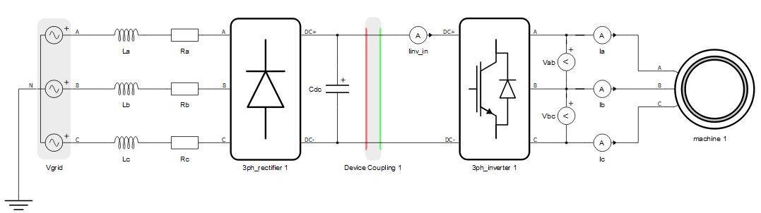
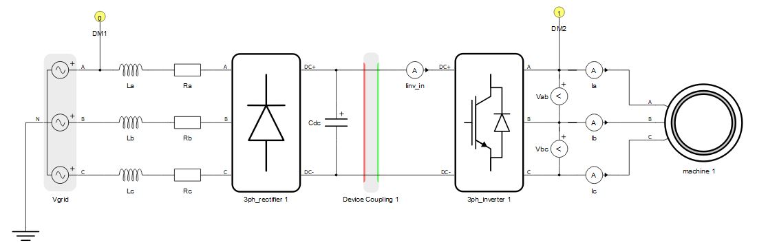
Secondly, circuits can be divided using both device couplings and core markers, which is shown in Figure 2. A device coupling is used to divide the full circuit into two separate circuits that should be emulated on two HIL devices. Device markers are used to define which part of the circuit is emulated in which HIL device. The rectifier part is marked with marker with id = 0, meaning that it is going to be emulated on the HIL device with ID 0. The inverter and the machine part of the circuit is marked with id = 1, meaning that it is going to be emulated on the HIL device with ID 1.
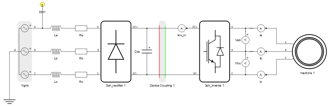
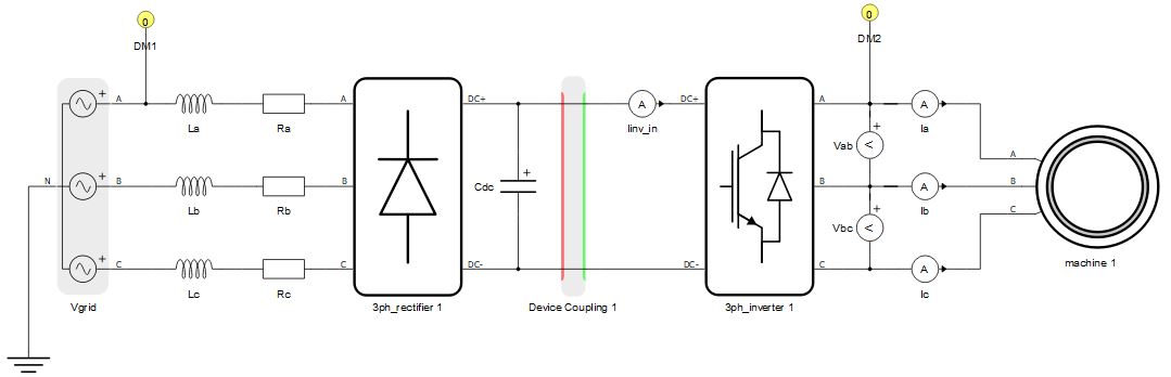
In multi-HIL configurations circuits device markers are mandatory while the use of coupling components is optional. Figure 3, Figure 4 and Figure 5 show examples of incorrectly divided circuits.