Recommended places for TLM coupling components
This section shows the general logic for determining the best spots for placing TLM coupling components through some common use cases.
Determining the position for a coupling component is crucial in order to preserve stability and accuracy of the simulation. In some cases, this step is trivial, while there are use cases when it is more challenging. For better results, coupling elements should be placed in the model where the dynamics in signals are lower.
These are general rules. It is not always possible to place a coupling component in an ideal position. TLM coupling brings an additional inductor or capacitor in the circuit, according to the selected coupling type. Because of that, our recommendation is to remove an existing inductor (or capacitor) from the circuit and then place the corresponding TLM coupling component at that spot. It is not recommended to measure voltage at the TLM coupling component. The following examples will illustrate some of the common circuit partitioning patterns.
Single phase inductive TLM coupling - Basic use cases
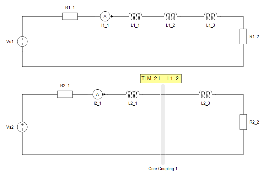
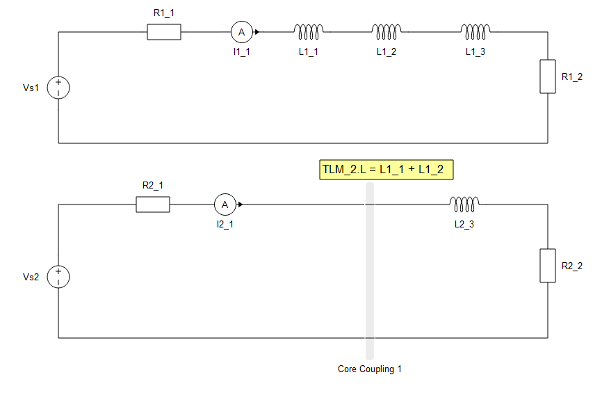
This pattern shows the basic principle of replacing existing inductor(s) with an inductive TLM link. This pattern can be used in every situation when a model contains inductor(s) in series with other elements. In this case, the inductor can be replaced with an inductive TLM single phase core coupling that has the same inductance as the replaced element. For example, in Figure 1, inductor L1_2 is replaced with a TLM coupling.
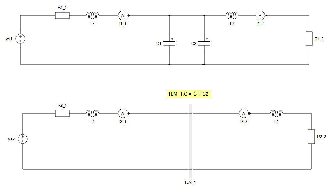
Single phase capacitive TLM coupling - Basic use case
The capacitive TLM coupling element can be used in a similar way to inductive TLM coupling elements. The only difference is that capacitor needs to be in parallel with the other elements. Figure 3 shows an example where capacitors C1 and C2 can be replaced with a capacitive TLM link that has a capacitance equal to the sum of C1 and C2.
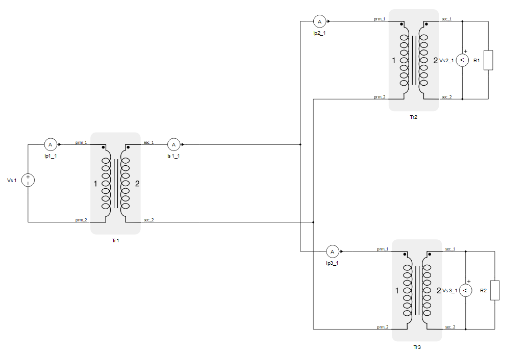
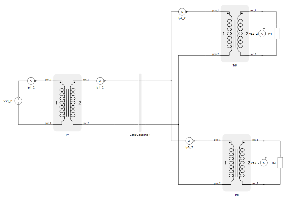
Single phase TLM coupling - transformers use case
When using TLM coupling elements next to a transformer, the goal is to divide an inductor at one of the transformer winding. Then, next to the changed winding, an inductive TLM coupling is placed. The sum of the coupling inductance and the "new" winding inductance needs to be the same as original winding inductance. Figure 4 shows the original circuit that needs to be decoupled. As mentioned earlier, the secondary winding inductance L can be reduced to L/2. Then, the inductive TLM coupling component can be added next to the transformer winding. The corresponding TLM inductance needs to also be L/2. The described procedure is shown in Figure 5.
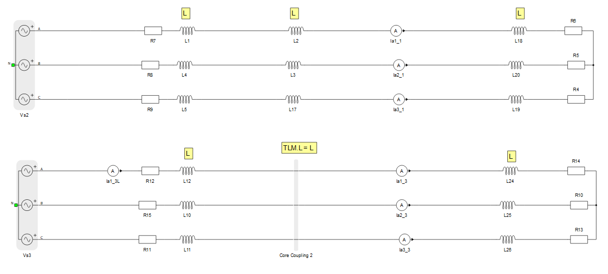
Three phase TLM coupling
Three phase TLM coupling is based on single phase TLM coupling. Therefore, there is no difference in usage recommendations. So, as in a single phase case, it is recommended to replace existing inductors (or capacitors) with a corresponding three phase TLM coupling element at that spot. Of course, the coupling inductance (capacitance) needs to be same as the inductance (capacitance) of the replaced element. Figure 6 shows one example of a three phase TLM coupling. Inductors labeled L2, L3, and L17 have an inductance L. They can be replaced with a three phase TLM core coupling element, with an inductance set to L. If inductances L2, L3, and L17 have different values, then a three phase coupling element must be implemented, combining the single phase TLM coupling components with different values.