Motor operated circuit breakers - ABB
This section describes ABB motor operated circuit breakers
| component | component dialog window | component parameters |
|---|---|---|
|
Single phase circuit breaker 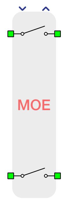
Two phase circuit breaker 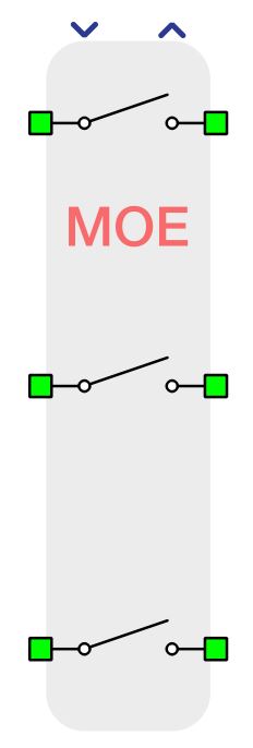
Three phase circuit breaker |
  |
|
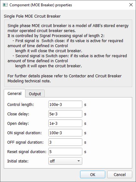
Breaker properties are described in Table 2.
| Group | Name | Description |
|---|---|---|
| General | Control length | Minimal length of control signal |
| Close delay | Close delay | |
| Open delay | Open delay | |
| ON signal duration | ON length | |
| OFF signal duration | OFF length | |
| Reset signal duration | Reset length | |
| Initial state | Breaker initial state | |
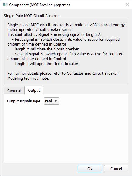
| Output | Output signals type | Choose the type of output signals |
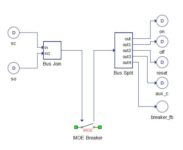
- First signal is used as an SWITCH CLOSE signal for the breaker
- Second is used as a SWITCH OPEN signal for the breaker
- First signal is the ON feedback from the breaker
- Second signal is the OFF feedback from the breaker
- Third signal is the RESET feedback from the breaker
- Fourth signal is the AUX_C feedback from the breaker
- Fifth signal is the breaker On/Off feedback
Figure 1 illustrates the proper way to connect the breaker's signals. In the example digital inputs and outputs are used.
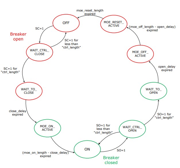
Circuit breaker model
From the electrical circuit point of view, the circuit breaker element is modeled as an ideal switch. Switch state is defined by a control FSM (Finite State Machine) block (Figure 2). The control FSM features two user-defined control inputs, SC (switch close) and SO (switch open). The output signal close controls the ideal switch. There are four additional output signals used as feed backs from the circuit breakers: MOE-ON, MOE-OFF, MOE-RESET, and AUX-C.
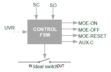
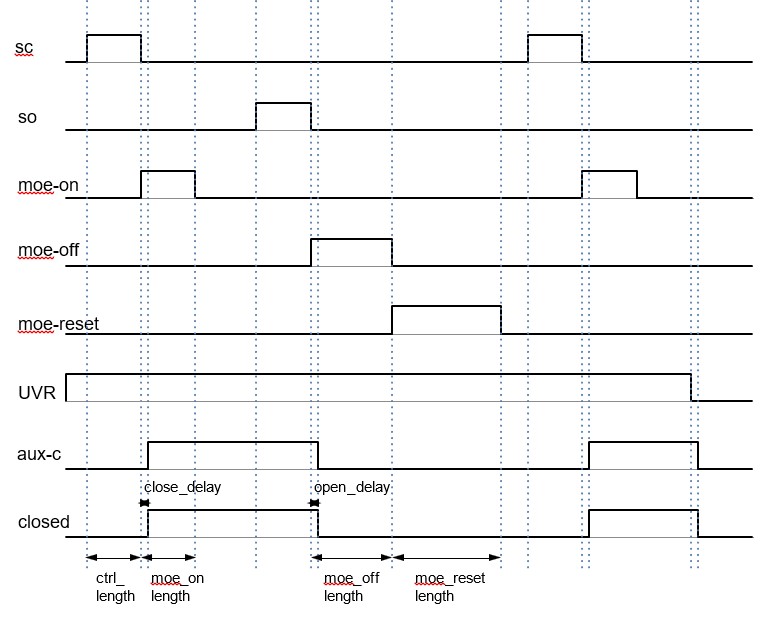
Control FSM function is defined by the state diagram in Figure 4.