Electric circuit partitioning
This section describes the general motivation for electrical circuit partitioning and gives some practical guidelines for using it in your model.
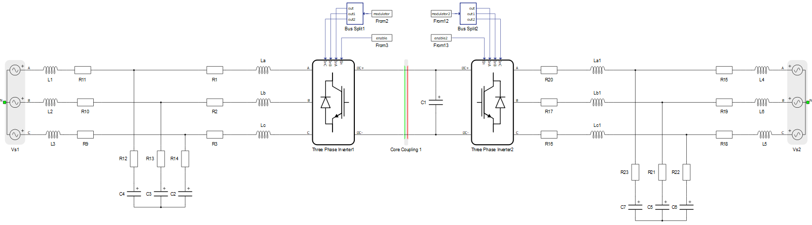
The core motivation for performing electric circuit partitioning is to enable parallel computing of complex power electronics and power system models that usually contain large number of switches. To demonstrate the benefits of this, we will use the example of a two-level back-to-back converter shown in Figure 1.
Converters are modeled using ideal switches, where a combination of a controllable switch (IGBT) and an anti-parallel diode are represented as one switch. The two-level back-to-back converter consists of two three-phase two-level converters, and each of them contains six switches.
Each switch permutation is represented by a linear time-invariant (LTI) state space matrix. For the circuit presented, that contains 12 switches, the number of permutation is 212 = 4096. In this case, 4096 state space matrices have to be stored. The memory capacity required to store the matrices rises exponentially as a function of number of switches.
If the circuit is split in two circuits, where each of them are executed on separate processors, or separate cores of a same processor, then the overall number of switch permutations per core is 26 = 64, and the overall number of matrices to be stored for both circuits is 2x64 = 128. This is significantly less than the 4096 required for one circuit.
On other hand, the time needed to simulate the circuit depends on the size and density of the state space matrices. If the full circuit is split, the matrices per core will be smaller, hence faster simulation rates can be achieved.
For further information about circuit partitioning, please refer to following pages:
Maximum number of communication lines between cores and devices
Coupling component placement and parametrization - Ideal Transformer based couplings
Coupling component placement and parametrization - TLM based couplings
Multi-HIL specific circuit partitioning
Additionally, an introduction to electrical circuit partitioning, covering the differences between Ideal Transformer and TLM based coupling, is available in our Video Knowledgebase and as part of the HIL Fundamentals course.