Port components
Description of the collection of Port components in Schematic Editor, which are used to connect internal subsystem elements to the outside schematic.
Component Icons
 |
 |
 |
| Electrical port | Signal Input port | Signal Output port |
Description
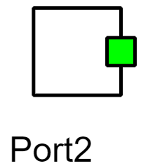
Port elements (Electrical port, Signal input port, and Signal output port components) are used to connect internal Subsystem elements to the outside schematic. For every port which is added, a corresponding terminal is created in the outer Subsystem element. Port properties can be set using the Port dialog window, which can be accessed by double-clicking the port element.
For more information on how to use subsystems to simplify models as part of a multi-level modeling approach, please refer to the Subsystem elements page.
Properties
- Side
- Specifies the side on which port terminal will be shown on the component.
- Index
- Specifies the index of the port terminal.
- Hide port name and terminal label
- Enables hiding port name and terminal label.
- Port terminal label
- Specifies the terminal label to display instead of the port name.