System architecture basics
This section explains the basic elements of the Typhoon HIL system and their functions: HILCore, User CPU, System CPU, Communication CPU, and Housekeeping CPU.
Real-time only: This document is valid only for real-time/VHIL
simulation.
Typhoon HIL simulators are based on a heterogeneous multi-processor architecture depicted in Figure 1.
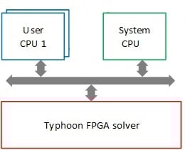
The basic elements of the system and their functions are:
- HILCore – specialized, proprietary FPGA-based multi-core processor(s) optimized for time-exact simulation of electrical domain models. HILCore solvers execute models at dedicated, nanosecond scale simulation steps.
- User CPUs – one or more general purpose processors that are under direct user control. They execute sub-models composed of signal processing components. The simulation step(s) is (are) user defined.
- System CPU – one general purpose processor that is directly controlled by the user. It is typically used to simulate low dynamics phenomena of certain electrical domain components. A few examples of components that utilize System CPU are RMS measurements and Constant Power Loads/Sources.
- Communication CPUs – one or more general purpose processors that execute applications for time-critical communication protocols, such as CAN Bus, CAN FD, Ethernet Variable Exchange, IEC 61850 Sampled Values protocol, and SPI protocol.
-
Housekeeping CPU – one general purpose processor that runs a Linux-based OS and is in charge of:
- HIL start-up sequence
- Communication with the PC
- Non-time-critical communication protocols
Figure 2 illustrates how different elements of a given model are mapped to the HIL device processing resources.
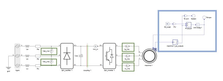
- Components framed by the green rectangle are fully or partially simulated on System CPU.
- Components framed by the blue rectangles are simulated on User CPU.
- All the remaining elements are simulated on HILCore solver.
Electrical domain modeling principles are explained in Electrical domain modeling principles and constraints.
Details about signal processing modeling are given in Signal processing modeling principles