OpenDSS & Typhoon HIL co-simulation
Demonstration of a simple power-flow analysis of a PV Plant using OpenDSS and Typhoon HIL real-time co-simulation.
Introduction
Power flow studies plays an important role in supporting decision making in the power systems field. Since modeling power flow with multiple load sources can be quite complex, several tools have been developed to facilitate power flow studies at the grid level. OpenDSS is a power distribution system simulator (DSS) from EPRI. In a nutshell, it allows you to solve the power flow for the fundamental grid frequency.
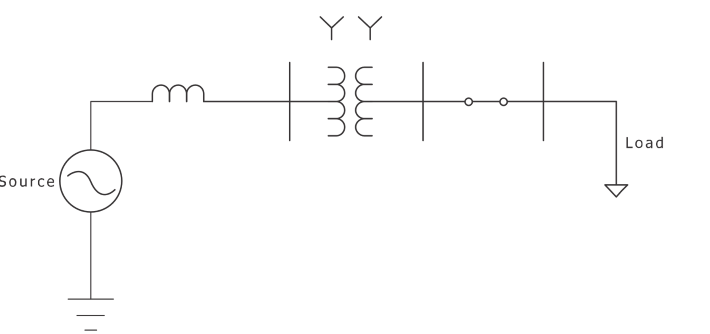
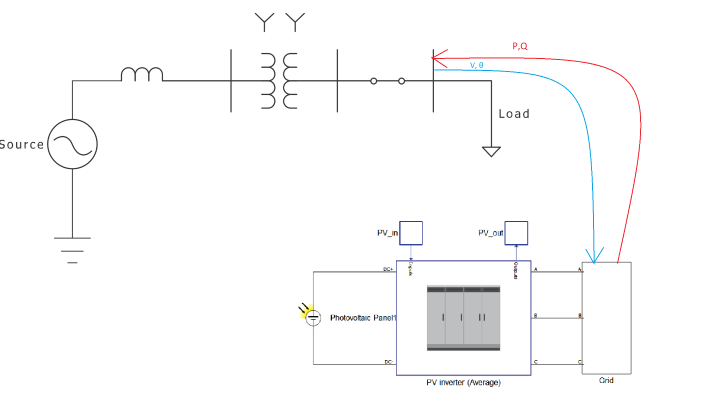
This example illustrates the application of the Typhoon HIL software in the field of Power Systems by co-simulation with the OpenDSS software. Typhoon HIL and OpenDSS can be interfaced together by means of a voltage-power exchange over the power system bus. That interface happens at the HIL SCADA level through Python APIs. It works by providing the OpenDSS simulation with information about power injections on a specific bus, solving a snapshot of the power flow, and then providing a new voltage setpoint at that same bus to the emulation running on the HIL device. On the OpenDSS side, the interfaced bus is any regular bus (P, Q node); on the Typhoon HIL side, the interfaced bus is a three-phase voltage source with a three-phase power measurement connected at its terminals.
Model description
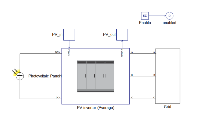
The model of the PV plant consists of a photovoltaic panel, an average model of a PV inverter, and a three-phase voltage source. The PV inverter (average) component is used directly from the https://www.typhoon-hil.com/documentation/typhoon-hil-software-manual/topics/microgrid.dita Library.

Simulation
This application comes with a pre-built SCADA panel shown in Figure 5. It offers the most essential user interface elements (widgets) to monitor and interact with the simulation at runtime, allowing you to further customize it according to your needs.
An OpenDSS installation is not required for Typhoon HIL Control Center to access the load flow solver on the same PC. Since the Typhoon HIL is Python-based, all you need in order to use the OpenDSS simulation is to import OpenDSSDirect.py in the Typhoon HIL SCADA initialization file. This is accessed via the Open panel intialization dialog button in the HIL SCADA menu bar. This file is a cross-platform Python package that implements a direct library interface to the OpenDSS engine. Finally, it is necessary to save all the files (.tse, SCADA etc.) in the same folder.
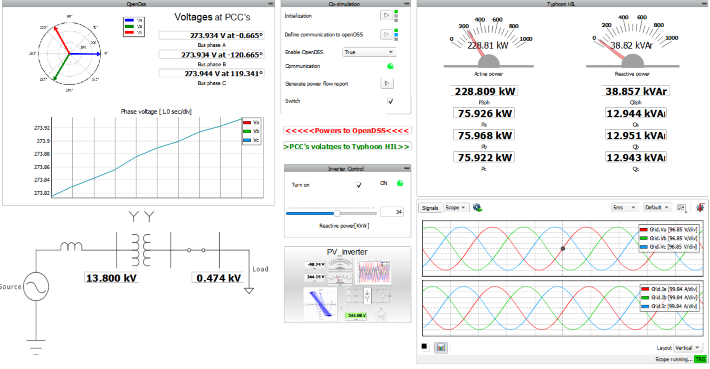
The functionality of this inverter is very straightforward. When the inverter is enabled, it will reach the maximum power point. There is also a possibility to set the reactive power in the Inverter Control options. For voltage-power exchange between the two models it is necessary to first enable communication and then turn the inverter on. There is also a contactor in OpenDSS controlled through HIL SCADA which should be closed. For the power flow report, it is necessary to click the Generate power flow report button.
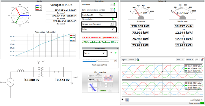
Figure 7 shows the power flow report in the case when the switch is closed. As the figure shows, the active and reactive power are almost equal with only small variations in values. This is due to the transformer, which has a series of inductances, as well as a magnetizing inductance.
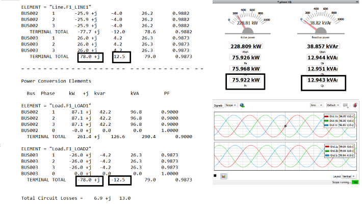
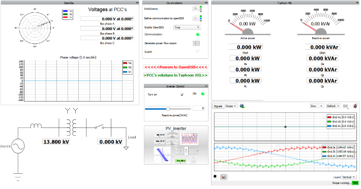
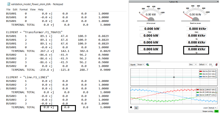
Figure 8 and Figure 9 demonstrate the case when the switch is open. In this case, the voltage on the common bus is 0, as are the powers that the inverter sends to OpenDSS.
Test automation
We don’t have a test automation for this example yet. Let us know if you wish to contribute and we will gladly have you signed on the application note!
Example requirements
Table 1 provides detailed information about the file locations and hardware requirements for running the model in real-time, followed by the HIL device resource utilization when running the model using this minimal hardware configuration. This information is provided to help you with running and customizing the model as you see fit.
| Files | |
|---|---|
| Typhoon HIL files |
OpenDSS and Typhoon HIL co-simulation opendss power flow co-simulation.tse opendss power flow co-simulation.cus opendss_model.dss PV_250KW.ipvx |
| Minimum hardware requirements | |
| No. of HIL devices | 1 |
| HIL device model | HIL402 |
| Device configuration | 1 |
| HIL device resource utilization | |
| No. of processing cores | 1 |
| Max. matrix memory utilization | 2.22% |
| Max. time slot utilization | 46.25% |
| Simulation step, electrical | 1 µs |
| Execution rate, signal processing | Multirate (50 µs, 100 µs, 1 ms, 0.5 s) |
Authors
[1] Jovana Markovic
[2] Simisa Simic