Wire interfacing
Recommendations for interfacing using wires
These methods are best applied when you want to bring up the setup fast, and there are no signal adaptation requirements, i.e. all analog signals fall within a ±10 V range. Once the setup is up and running, moving to a more reliable setup is recommended.
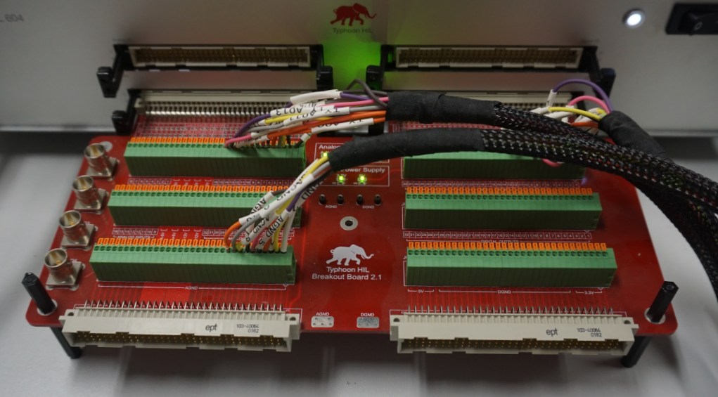
HIL Breakout Board
To enable a fast start, Typhoon HIL has designed an interface board, featuring spring-cage connectors which break out all signals from the connected HIL. These connectors hold bare copper wires in place via spring-type contacts, which are actuated by a finger or a small screwdriver. An example of such a setup, featuring a HIL Breakout Board 2.1, is shown in Figure 1.
For more information please visit the HIL Breakout Board product documentation.
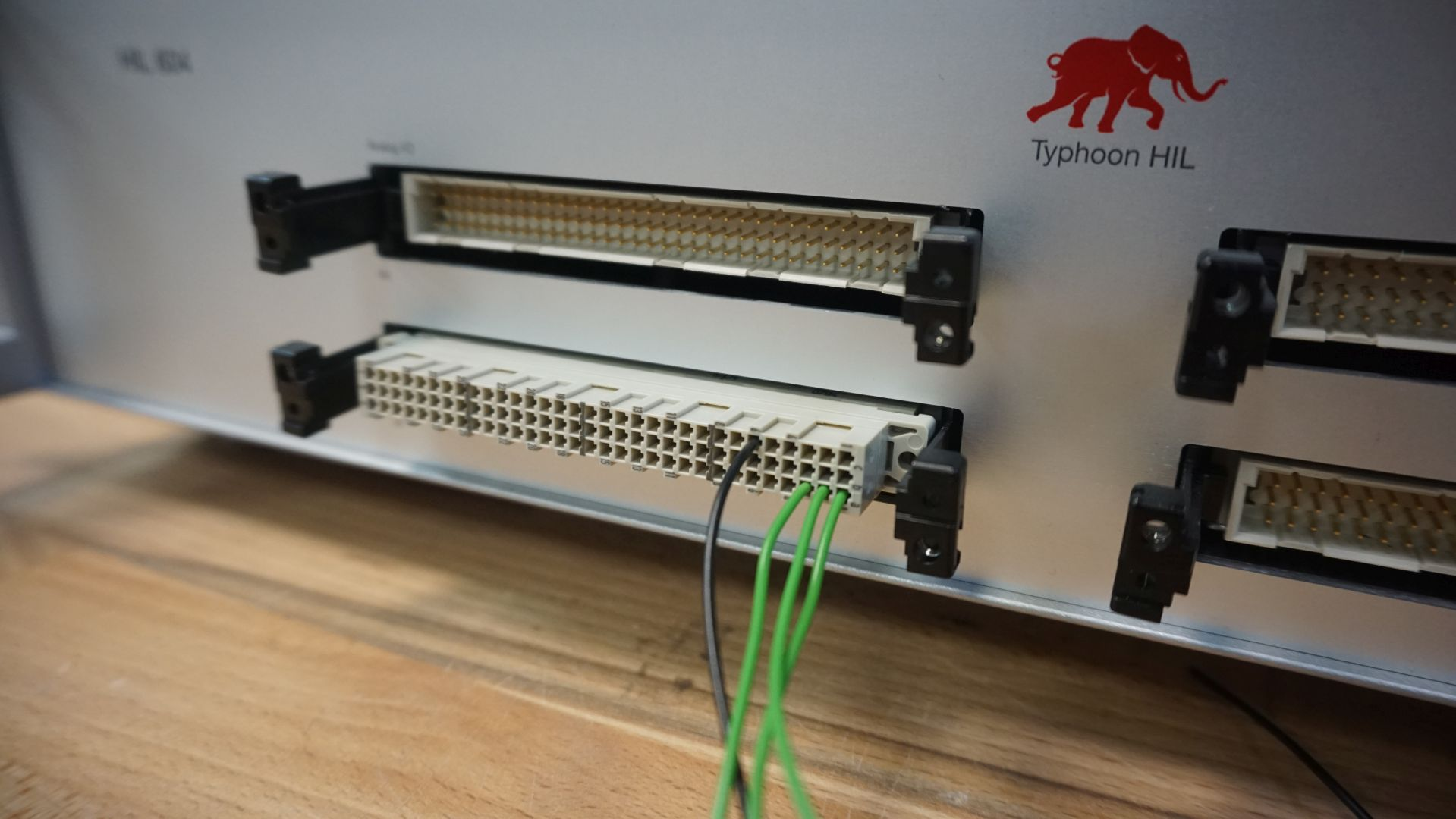
DIN41612 crimp connector
If no HIL Breakout Board is available, the preferred method is to use a DIN41612 connector which provides access to individual wires. An example of such a connector is HARTING 09030963214, as illustrated in Figure 2.
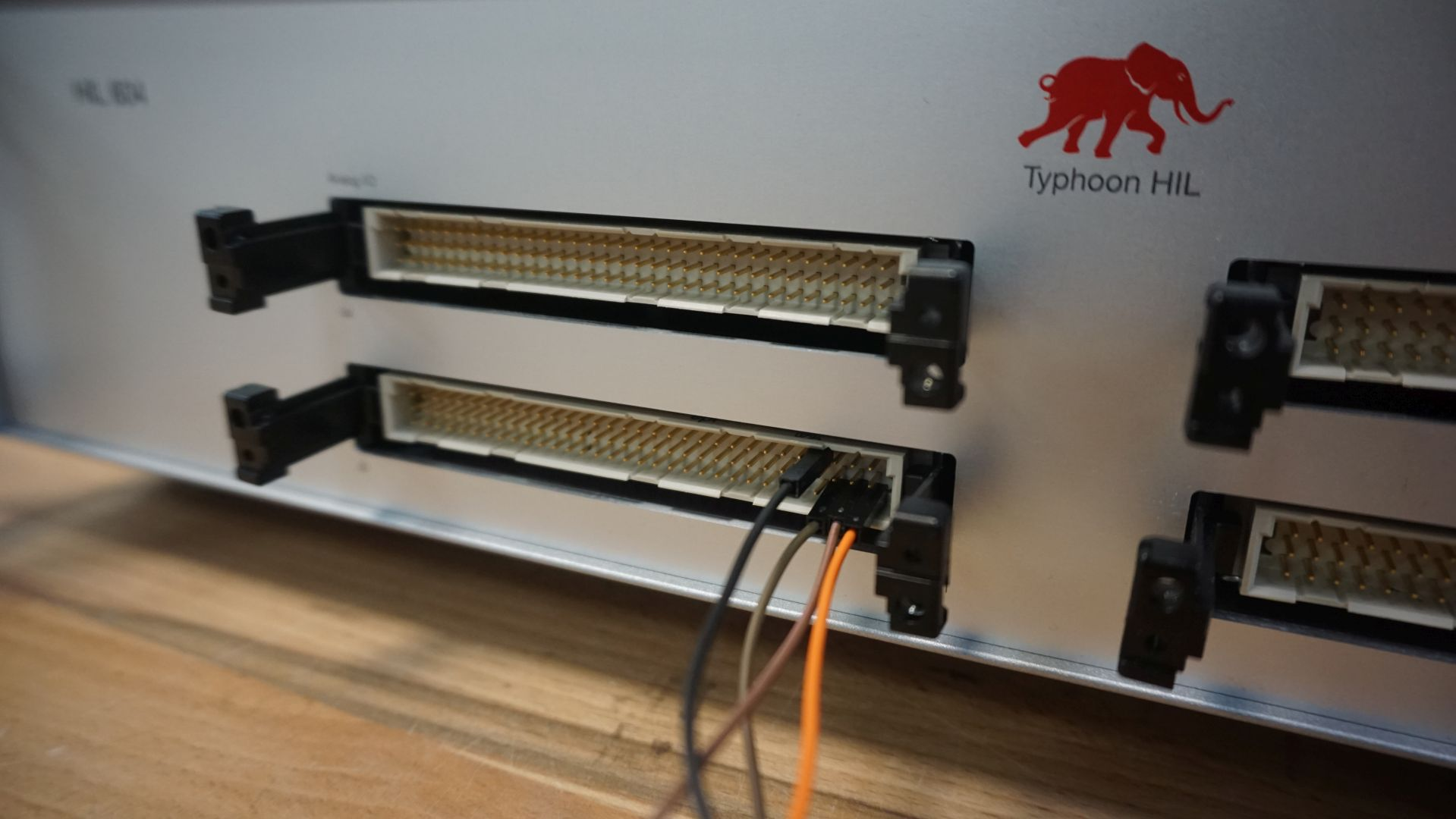
Jumper wires
Another option for a fast start is the use of jumper wires, as illustrated in Figure 3.
Recommended material or supplies
| Part Number | Manufacturer | Description |
|---|---|---|
| 20001 | Typhoon HIL | HIL Breakout Board (see documentation) |
| PRT-09390 | SparkFun Electronics | Jumper Wires Premium 12" F/F Pack of 100 |
| PRT-09386 | SparkFun Electronics | Jumper Wires Premium 12" M/F Pack of 100 |
| 09030963214 | HARTING | DIN41612 connector housing, 96 pin, for crimped wires, 20-28AWG |
| 09020008484 | HARTING | Crimp contact for DIN41612 connector housing, 20-28AWG |