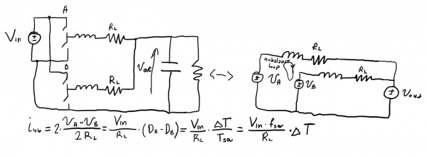
Let's consider an interleaved buck converter, consisting of two legs A and B. We want to understand the origin and estimate the value of a current imbalance that can occur.
In order to analyze the circuit, we can assume a continuous conduction mode. In such operation, the average output voltages at the switch node are given with va = Da*Vin, vb = Db*Vin. Current unbalance will occur if there is some difference in duty cycles. If we express this difference in terms of duration, we can derive a generalized equation to calculate the current, as shown in the image.

In a real-world system, even if PWM modulator is programmed perfectly, the uncertainty will always exist with regards to signal propagation in the system due to the multiple reasons. Imperfection of passive components that are incorporated into the digital output/digital input circuit design will inevitably change the time constants of input/output impedances. There is also always uncertainty with regards to IO voltage levels - We specify that the minimum voltage value at which logic-high is detected is 2V, while maximum logic-low level is 0.8V, but we cannot be certain when exactly will the logic level change be detected. This will reflect into uncertainty of pulse duration as well.
In order to estimate the impact of the pulse length difference, let's assume that all the uncertainties add up to a single sample of a difference in pulse lengths of two legs - 3.5ns. If input voltage is 650V, fsw is 200kHz and RL is 10mOhm, the formula yields 45.5A of current unbalance between two legs! This means that even a very small difference in pulse length will cause a significant current unbalance. Therefore, we shall not expect the current to be perfectly balanced when using HIL IO loopback, or the external controller in open-loop.
Interestingly, HIL will be able to capture even 1ns of pulse length difference if the external controller is used, even though the DI sampling rate is 3.5ns. Since the controller isn't synchronized with HIL in any way, duty cycle that's measured will not be constant between multiple switching periods. The average value of detected duty cycle will reflect the 1ns difference, which will be reflected in the simulation results, yielding 13A of current unbalance. This can be confirmed by using PWM Analyzer to measure the average duty cycle over long time span.
Finally, when running on the actual power hardware, uncertainties will be increased due to the fact that turn on/turn off delays on real power MOSFETs have ranges that are often 10s of nanoseconds. For this reason, one should always make sure to actively balance the currents.