Thermal network
The Thermal Network component implements a signal processing model of a thermal system that can be parametrized with either Cauer or Foster thermal model data.
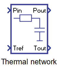
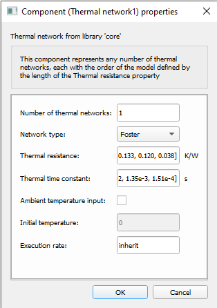
Component Icon
Description
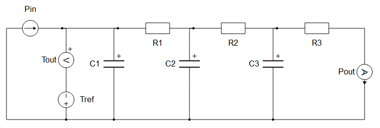
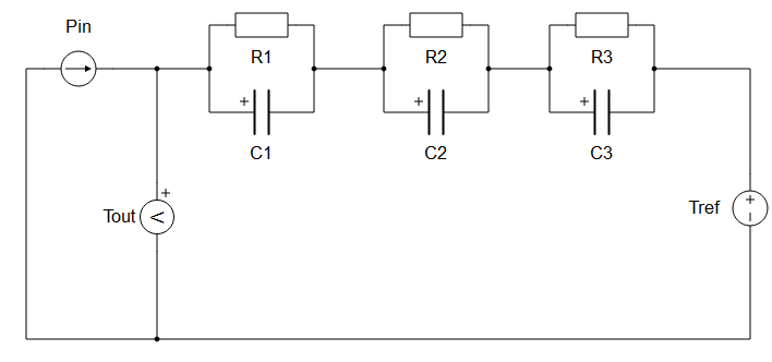
This component represents any number of general thermal networks, each with a model order defined by the length of the thermal resistance property. The represented models can be parametrized with either Cauer or Foster thermal model data. Cauer model parameters have physical meanings, representing thermal resistance and thermal capacitance of an object seen in Figure 2. The Foster model type is a purely mathematical representation of a thermal system. Parameters of this type can be obtained from real measurements, but the voltages of each terminal no longer represent any particular physical value. The electrical equivalent model seen in Figure 3. Therefore, if the model is parametrized as Foster network type, the given parameters will automatically be translated to a Cauer thermal model before the start of the simulation. The number of resistances and capacitors in the electrical equivalent circuit for both models depends on the length of the Thermal resistance parameter.
Inputs and outputs can be either scalars or vectors. This depends on the component's Number of thermal networks property. If the number of thermal networks is equal to 1, inputs and outputs are scalars. If the number of thermal networks is greater than 1, inputs and outputs are vectors with length corresponding to this property.
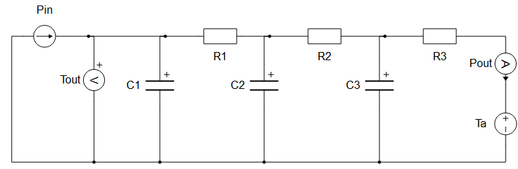
If the check box Ambient temperature input is ticked, the equivalent electrical circuit will be represented as in Figure 4. If the Foster network is simultaneously enabled, the new ambient temperature change will only be applied after the parameters are translated to the Cauer model type.
Ports
- Pin (in)
- Power input to the Thermal network(s) in [W]
- Supported types: real.
- Vector support: yes.
- Power input to the Thermal network(s) in [W]
- Tref/Ta (in)
- Reference temperature for Thermal network(s) in [°C] or [K]
- Supported types: real.
- Vector support: yes.
- Ambient temperature for Thermal network(s) in [°C] or [K]
- Supported types: real.
- Vector support: yes.
- Reference temperature for Thermal network(s) in [°C] or [K]
- Pout (out)
- Output power from the Thermal network(s) in [W].
- Supported types: real.
- Vector support: yes.
- Output power from the Thermal network(s) in [W].
- Tout (out)
- Output temperature from the Thermal network(s) in [°C] or [K] (inherited
from Tref).
- Supported types: real.
- Vector support: yes.
- Output temperature from the Thermal network(s) in [°C] or [K] (inherited
from Tref).
Properties
- Number of thermal networks
- Number of thermal networks that will be internally created. This number also defines the vector size of the input and output signals. All created thermal networks will be parametrised with the same values inserted on the mask of the component. This parameter must be an integer greater than 0.
- Network type
- Defines the type of thermal network(s)
- Thermal resistance
- Thermal resistance values. This parameter must be either a list of values or a single value. The number of elements must be the same as for Thermal time constant and Thermal capacitance parameters.
- Thermal time constant/ Thermal capacitance
- Thermal time constant values when the Foster network type is selected. The number of elements must be the same as for the Thermal resistance parameter.
- Thermal capacitance values when the Cauer network type is selected. The number of elements must be the same as for the Thermal resistance parameter.
- Ambient temperature input
- Changes the topology of the thermal network. If switched on, signal processing correlates to ambient temperatures in comparison to the default reference temperature.
- Initial temperature
- Defines the initial temperature of the thermal network(s) in Celsius. This property is enabled and evaluated only when the "Ambient temperature input" property is enabled. In the other scenario, the 'Tref ' input already represents the initial temperature.
- Execution rate
-
Type in the desired signal processing execution rate. This value must be compatible with other signal processing components of the same circuit: the value must be a multiple of the fastest execution rate in the circuit. There can be up to four different execution rates, but they must all be multiple of the basic simulation timestep. To specify the execution rate, you can use either decimal (e.g. 0.001) or exponential values (e.g. 1e-3) in seconds. Alternatively, you can type in ‘inherit’ in which case the component will be assigned execution rate based on the execution rate of the components it is receiving input from.
-