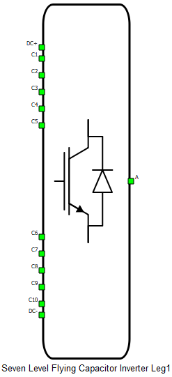
Seven level flying capacitor leg
This section describes the seven level flying capacitor leg
| component | component dialog window | component properties |
|---|---|---|
 Seven Level Flying Capacitor Leg |
 |
|
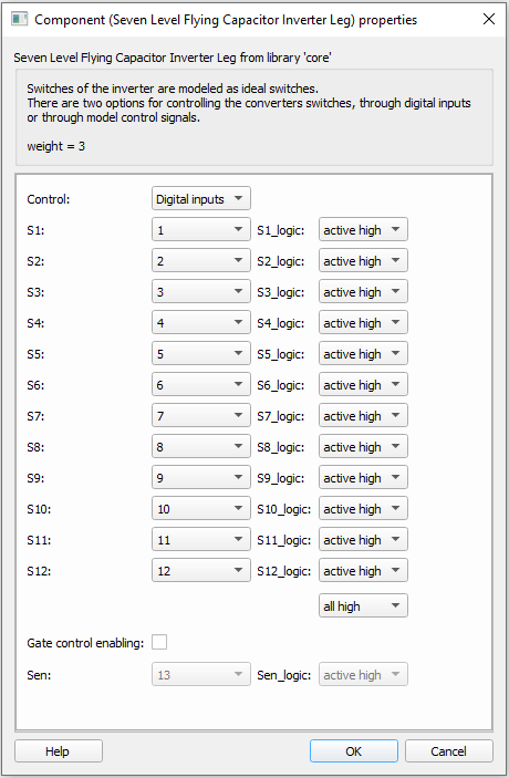
Digital inputs, when selected for Control parameter, enables the user to assign gate drive inputs to any of the digital input pins.For example, if S1 is set to 1, the digital input pin 1 will be routed to the S1 switch gate. In addition, the S1_logic parameter selects either active high (High-level input voltage VIH turns on the switch), or active low (Low-level input voltage VIL turns on the switch) gate logic, depending on the user’s external controller design.
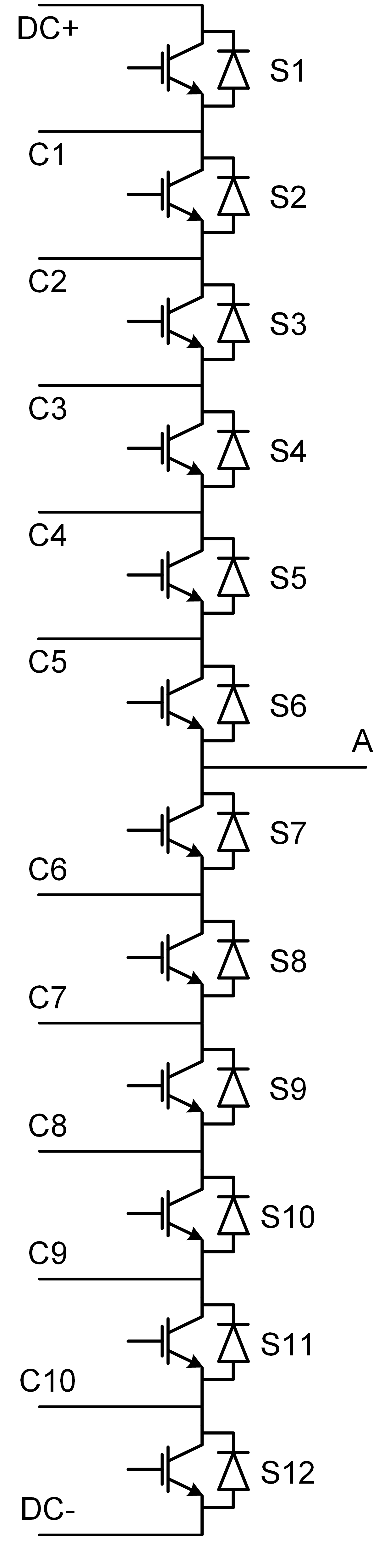
Model, when selected for Control parameter, enables the user to set the IGBTs gate drive signals directly from signal processing model. The input pin gates appears on the component and requires a vector input of twelve gate drive signals in the following order: [S1, S2, S3, S4, … , S12]. When controlled from the model, logic is always active high.
Gate control enabling, when checked, enables using an external PWM enabling digital signal.
Digital Alias
If a converter is controlled by digital inputs, an alias for every digital input used by the converter will be created. Digital input aliases will be available under the Digital inputs list alongside existing Digital input signals. The alias will be shown as Converter_name.Switch_name, where Converter_name is name of the converter component and Switch_name is name of the controllable switch in the converter.