NPC PV Inverter
This section describes the 3-level NPC PV Inverter component.
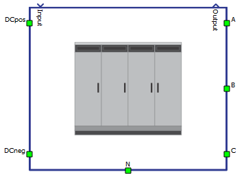
This Schematic Editor component block from the Microgrid category models a low-voltage, photovoltaic solar inverter implemented with a three-phase three-level neutral point clamped inverter, rated at 1 MVA @ 480V L-L.
Cascaded control loops consist of a current controller (resonant control in alpha-beta coordinates with 5th, 7th and 11th harmonic rejection), an open-loop power controller (based on instantaneous grid voltage), and an energy-based DC voltage controller with a fixed-step MPPT algorithm.
The DC link is open for connection to a PV panel component with a maximum power point around the rated value of 1000 VDC. This inverter implements a modulation strategy to internally keep the capacitor-created DC midpoint voltage at half of the total DC voltage.
The reactive power is defined in terms of a desired power factor and a direction (inductive or capacitive). The power controller allows for P, Q, or power factor priority in situations of power saturation (references greater than the maximum allowed power).
The start-up procedure is implemented as follows: once grid voltages and frequency are in the allowable range, the grid contactor will be closed. After that, if the inverter enable input is true, the inverter will start switching and the system will look for the maximum power point for the connected PV panel. This inverter will ramp up the references on start-up.
This NPC PV inverter implements voltage and frequency ride-through functionality according to UL 1741 SA with Rule 21 requirements. See Voltage and Frequency ride-through for details.
| component | component dialog window | component parameters |
|---|---|---|
 |
 |
|
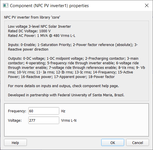
Inputs
| Number | Name | Description |
|---|---|---|
| 0 | Inverter Enable | Enables operation of the inverter. Note that grid contactor control is independent from this command. |
| 1 | Power Saturation Priority | Defines priority when requested set-points are higher than maximum allowed power. Setting = 0 ensures active power priority. Setting = 1 ensures reactive power priority. Setting = 2 preserves power factor (reduces P and Q proportionally). |
| 2 | Reference Power Factor | Desired power factor for inverter output power (between 0 and 1). |
| 3 | Reactive Output Power direction | Direction for the reactive output power. Setting +1 means output reactive power is capacitive (supplying to the grid), -1 means it is inductive (consuming from the grid). |
Outputs
| Number | Name | Description |
|---|---|---|
| 0 | DC link Voltage | Measurement of total DC link voltage. |
| 1 | DC link midpoint Capacitor Voltage | Measurement of midpoint capacitor DC link voltage. In normal operation should be half of total voltage. |
| 2 | Pre-charging Contactor | Digital signal active when pre-charging contactor is closed. |
| 3 | Main grid Contactor | Digital signal active when main grid contactor is closed. |
| 4 | Operating | Digital signal active when all start-up procedures are finished and inverter is operating with all control functions. |
| 5 | Frequency ride-through inverter enable | Digital signal active when inverter should not be subject to a trip because of frequency ride-through protection. |
| 6 | Voltage ride-through inverter enable | Digital signal active when inverter should not be subject to a trip because of voltage ride-through protection. |
| 7 | Voltage ride-through references enable | Digital signal active when inverter should not zero the power injected to the grid because of voltage ride-through protection. |
| 8 | Grid RMS Voltage phase A | - |
| 9 | Grid RMS Voltage phase B | - |
| 10 | Grid RMS Voltage phase C | - |
| 11 | Grid RMS Current phase A | - |
| 12 | Grid RMS Current phase B | - |
| 13 | Grid RMS Current phase C | - |
| 14 | Grid frequency | - |
| 15 | Grid injected Active Power (P) | - |
| 16 | Grid injected Reactive Power (Q) | - |
| 17 | Grid injected Apparent Power (S) | - |
| 18 | Grid injected Power Factor | - |
Voltage and Frequency ride-through
This inverter implements frequency and voltage ride through according to UL 1741 SA with Rule 21 requirements. A summary of the settings can be found in the following tables:
| Region | Voltage (% Nominal Voltage) | Ride-Through Duration (s) | Operating Mode | Maximum Trip Time (s) |
|---|---|---|---|---|
| High Voltage 2 (HV2) | V ≥ 120 % | 0.16 | ||
| High Voltage 1 (HV1) | 110 % < V < 120 % | 12 |
Momentary Cessation (gate blocking) |
13 |
| Near Nominal (NN) | 88 % ≤ V ≤ 110 % | Indefinite | Continuous Operation | Not Applicable |
| Low Voltage 1 (LV1) | 70 % ≤ V < 88 % | 20 | Mandatory Operation | 21 |
| Low Voltage 2 (LV2) | 50 % ≤ V < 70 % | 10 | Mandatory Operation | 11 |
| Low Voltage 3 (LV3) | V < 50 % | 1 |
Momentary Cessation (gate blocking ) |
1.5 |
| Region | System Frequency Default Settings | Frequency in pu | Ride-Through Duration (s) | Ride-Through Operational Mode | Trip Time (s) |
|---|---|---|---|---|---|
| High Frequency 2 (HF2) | f > 62 | f >1.0083 | No Ride-Through | Not Applicable | 0.16 |
| High Frequency 1 (HF1) | 60.5 < f < 62 | 1.033 < f < 1.0083 | 299 | Mandatory Operation | 300 |
| Near Nominal (NN) | 58.5 < f < 60.5 | 0.975 < f < 1.0083 | Indefinite | Continuous Operation | Not Applicable |
| Low Frequency 1 (LF1) | 57.0 < f < 58.5 | 0.95 < f < 0.975 | 299 | Mandatory Operation | 300 |
| Low Frequency 2 (LF2) | f < 57.0 | f < 0.95 | No Ride-Through | Not Applicable | 0.16 |
Example
Overall behavior and control methodologies can be better understood with the use of the given example:
Model name: npc_pv_inverter.tse
SCADA interface: npc_pv_inverter.cus
Path: /examples/models/microgrid/npc_pv_inverter/
Acknowledgements
This component was developed with partnership with Federal University of Santa Maria's Power Electronics and Control group (GEPOC) in Brazil, represented by prof. Humberto Pinheiro, Ph.D and team.