Non-ideal
Description of non-ideal contactors in Schematic Editor
The Non-Ideal sub-folder of the Contactors library category contains single and three phase contactors modeled as non-ideal switches, shown in Table 1. Switches are modeled as a small inductance while conducting and small capacitance when open.
| component | component dialog window | component parameters |
|---|---|---|

Single phase non-ideal contactor |
|
|
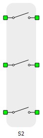
Three phase non-ideal contactor |
|
|

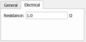
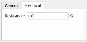
The parameter Resistance and the simulation step are defining the actual inductance and capacitance values according to the following equations:
Where L and C are the calculated inductance and capacitance, Ts is the simulation step of electrical part of the model, R is the set resistance value.
Digital Alias
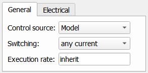
If the contactor is controlled by digital input, the alias for digital input used by contactor will be created. The digital input alias will be available under the Digital inputs list alongside the existing Digital input signals. The alias will be shown as Contactor_name.Switch_name, where Contactor_name is the name of the contactor component and Switch_name is the name of the controllable switch in the contactor.