MMC Leg - Switching Function
This section describes the MMC Leg based on a switching function model.
Control for MMC Leg - NLC is a compatible component in our library for internal control the MMC Leg - Switching Function.
| component | component dialog window | component properties |
|---|---|---|
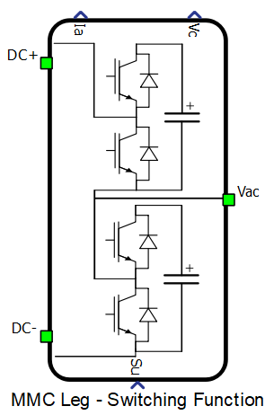 MMC Leg - Switching Function |
 |
|
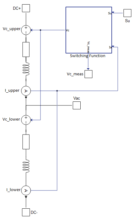
MMC Leg - Switching Function is composed of two arms - upper and lower. Each arm consists of a series connection of voltage source (Vc_upper and Vc_lower), resistor, inductor and current measurement (I_upper and I_lower) shown in schematic block diagram below. Voltage source is controlled by Switching Function block (it replaces all capacitors and switches in arm) and represents a sum of all voltages across capacitors that are currenlty inserted in the arm. Inputs in this block are current measurements of both arms and an array Su which represents switching states for each sub-module. For example, in case when the value of element in the array Su is equal to 1, current will flow through the capacitor and if the value of element is equal to 0, current will bypass the capacitor. Number of voltage levels is determined by the length of array Su.
Inputs and outputs
The MMC Leg - Switching Function component needs one input to operate. This input must be sent as an array and the following table describes it.
MMC Leg -Switching Function input
| Input | Description |
|---|---|
| Su | A digital input that determinates which sub-modules will be inserted in the circuit. |
The MMC Leg - Switching Function has 2 outputs. They are organized as an arrays and they are described in the following table.
MMC Leg - Switching Function outputs
| Output | Description |
|---|---|
| Ia | The measured currents in both arms are provided as an array through analog output. |
| Vc | The measured voltages across the capacitors in both arms are provided as an array through analog output. |
Component dialogue box and parameters
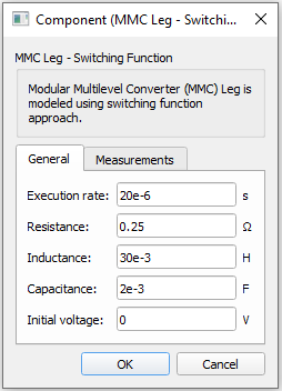
The MMC Leg - Switching Function component dialogue box consists of two tabs for specifying general parameters and for enabling measurements.
Tab: "1 - General"
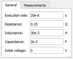
MMC Leg - Switching Function model "1 - General" parameters
| Parameter | Code name | Description |
|---|---|---|
| Execution rate | ex_rate | Execution rate of all signal processing components in a model.[s] |
| Resistance | rd | Arm resistance. [Ω] |
| Inductance | ld | Arm inductance. [H] |
| Capacitance | cm | Capacitance of each capacitor in a leg. [F] |
| Initial voltage | init_vol | Initial voltage across each capacitor in a leg. [V] |
Tab: "2 - Measurements"
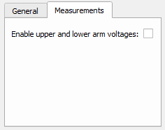
MMC Leg - Switching Function model "2 - Measurements" parameters
| Parameter | Code name | Description |
|---|---|---|
| Enable upper and lower arm voltages | vol_arm | Enables observation of instantaneous voltage signals, separately in upper and lower arm. |