Grid Fault
Description of the Grid Fault component in Schematic Editor.
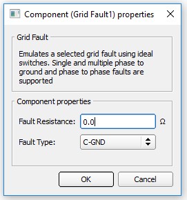
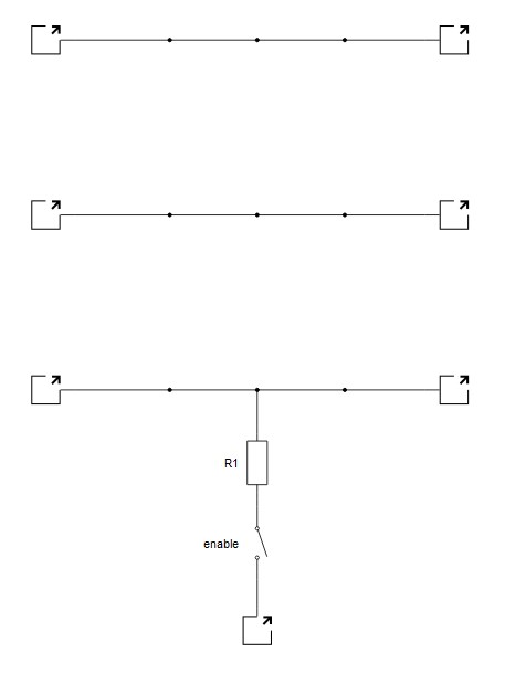
The Grid Fault component emulates a fault on a three phase grid using ideal switch. The fault type can be chosen by selecting one of the eleven fault types in a combo box in the Properties window of the component. A fault resistance can be defined; by default it is zero. Depending on the chosen fault type, the internal structure of the component is changed and an ideal switch is placed according to a chosen fault type. The internal structure of grid fault for C-N fault is shown in Figure 1. In Table 1 the Schematic Editor symbol and the Properties window of the grid simulator are shown.
| component | component dialog window | component parameters |
|---|---|---|
Grid fault |
 |
|
List of available digital feedbacks of the grid fault is shown in Internal digital measurements of the Grid Fault
Internal digital measurements of the Grid Fault
| Analog output variable name | Description |
|---|---|
| (name).single_ph_sw_fb | Digital feedback of the internal switch. |